Novel structure motor driver

A technology of motor driver and new structure, which is applied in the direction of motor control, AC motor control, and transformation of equipment structure parts, etc. It can solve problems such as unreasonable capacitance distribution, difficult circuit layout and mechanical installation layout, and fast temperature rise of the driver. Improve the current passing ability, facilitate automatic production, and have the effect of strong current passing ability

Pending Publication Date: 2018-07-10
林锋
View PDF0 Cites 2 Cited by
  • Summary
  • Abstract
  • Description
  • Claims
  • Application Information

AI Technical Summary

Problems solved by technology

The structural design of the motor driver has a great influence on the performance of the driver. The existing structural design of the driver is unreasonable, especially the distribution of the power drive part and the capacitor is unreasonable. For example, the existing half-bridge module generally includes multiple sets of power tube devices , multiple positive terminals, multiple negative terminals, and power bus filter capacitors, so many components bring difficulties to the circuit layout and mechanical installation layout. As the temperature rises, the output power drops significantly, so the output power of the driver cannot be maintained to the maximum extent. The reasons for this situation are as follows:
[0003] 1. The capacitance distribution is unreasonable in structural design, so that in practical applications, the cap

Method used


Image

  • Novel structure motor driver
  • Novel structure motor driver
  • Novel structure motor driver

Examples


Example Embodiment

[0027] The specific embodiments of the present invention will be further described below in conjunction with the drawings and embodiments. The following embodiments are only used to illustrate the technical solutions of the present invention more clearly, and cannot be used to limit the protection scope of the present invention.

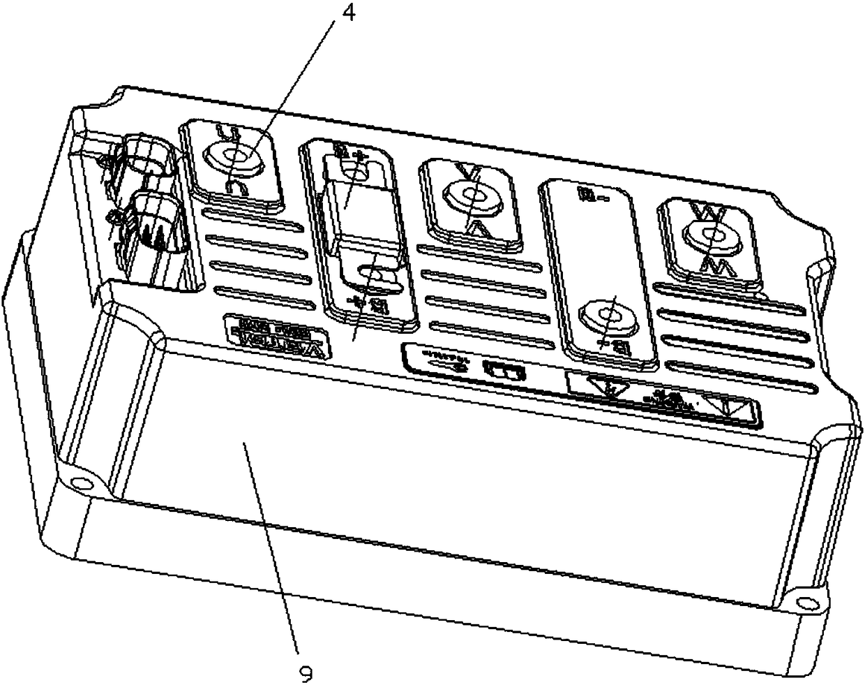
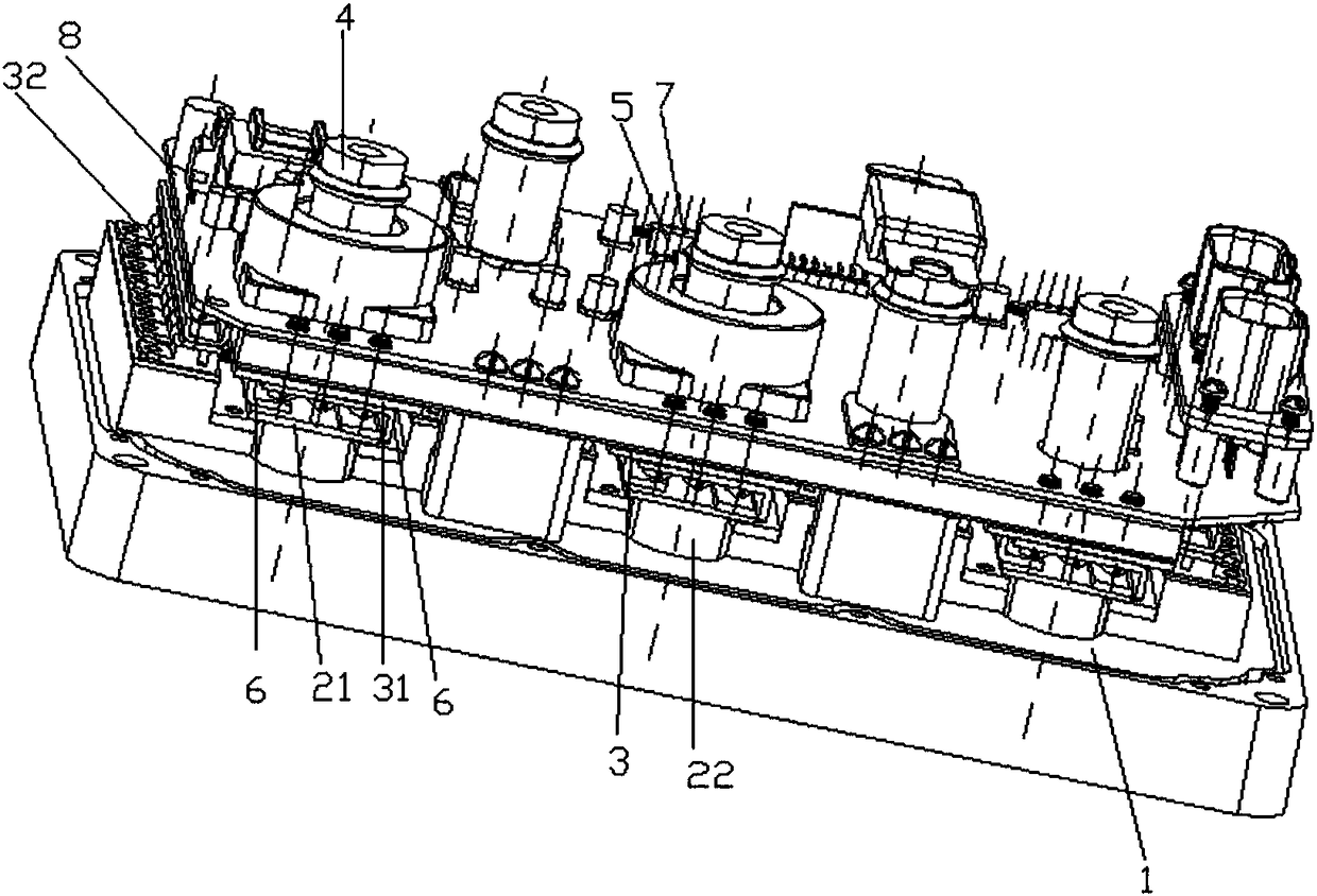
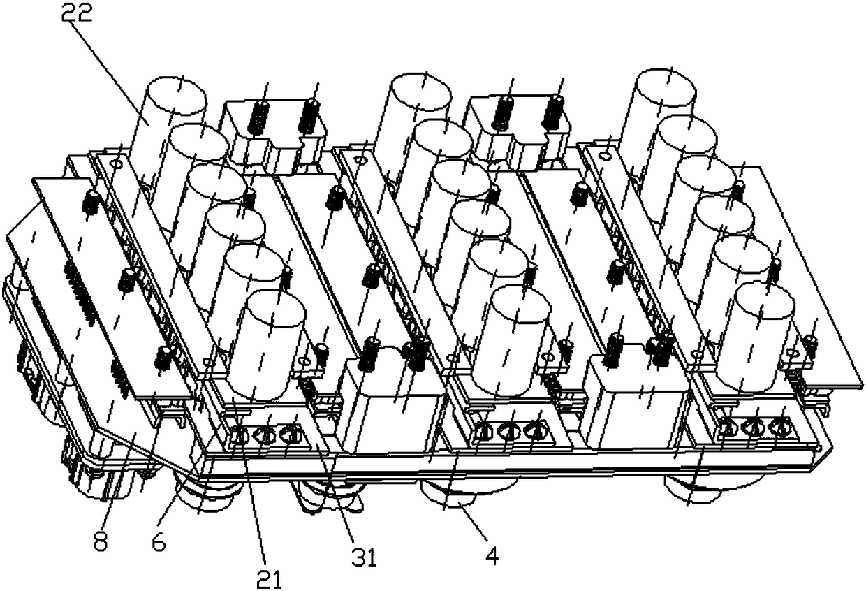
[0028] Such as figure 1 , 2 As shown in and 3, a new structure of the motor driver includes a capacitor module part 2 and a power drive module part 3, an aluminum shell 1 and a plastic shell 10 for packaging. The aluminum shell 1 is used as the shell to carry the capacitor module part 2 and The power drive module part 3 and the capacitor module part 2 include six compensation and filtering capacitors 22 uniformly distributed in a row on the capacitor PCB 21. The capacitors 22 are embedded in the aluminum housing 1. The capacitor 22 and the aluminum housing 1 The gap between the gaps is filled with thermally conductive silicone grease to enhance the ther...


PUM


Abstract

The invention discloses a novel structure motor driver. A capacitor module part comprises capacitors uniformly distributed on capacitor PCBs (printed circuit board) in an l shape; the capacitors are arranged in a way of being embedded in an aluminum case; a power module busbar copper sheet is welded and arranged on the power module PCBs; power tubes are uniformly arranged at the two sides of the power module PCBs in lines; an output copper post is also arranged on the power module PCB; board to board connection plug pins are arranged on board to board connection pin seats; the capacitor PCBs are connected with positive and negative electrode copper strips of a power module on the power module PCBs through screws. The novel structure motor driver also comprises a main control PCB arranged at the upper part of the power module PCBs; the main control PCB and the power module PCBs are communicated through a positive and negative electrode busbar copper strip; a control part circuit is provided with a branch circuit for collecting voltage drop in the work process of the power device and directly collecting output current of the power device by a current sensor. The novel structure motordriver has the advantages that the structure is optimized and more reasonable; the capacitance can achieve the capacitor compensation current features to the maximum degree; partial heating quantityof the power module is reduced; the heat radiation condition is improved.

Description

technical field [0001] The invention relates to the technical field of drivers, in particular to a motor driver with a new structure. Background technique [0002] The motor controller receives the DC output from the battery, and converts the DC power into a three-phase AC output, so each power module part corresponds to one phase of the three-phase power, and is used to output U, V, W three-phase power to the motor of one-phase power supply. The structural design of the motor driver has a great influence on the performance of the driver. The existing structural design of the driver is unreasonable, especially the distribution of the power drive part and the capacitor is unreasonable. For example, the existing half-bridge module generally includes multiple sets of power tube devices , multiple positive terminals, multiple negative terminals, and power bus filter capacitors, so many components bring difficulties to the circuit layout and mechanical installation layout. As t...

Claims


Application Information

Patent Timeline
IPC IPC(8): H02P25/16H02M7/00H02P29/68
CPCH02M7/003H02P25/16H02P29/68
Inventor 林锋
Owner 林锋
Why Eureka
Try Eureka