Control system and control method

a control system and control method technology, applied in mechanical equipment, transportation and packaging, gearing, etc., can solve the problems of deteriorating fuel economy, increasing exhaust gas, and consuming energy, and achieves quick start-up of the engine, increase the transmission torque capacity of the clutch, and increase the engine rotation speed

Active Publication Date: 2016-08-11
TOYOTA JIDOSHA KK
View PDF0 Cites 10 Cited by
  • Summary
  • Abstract
  • Description
  • Claims
  • Application Information

AI Technical Summary

Benefits of technology

[0010]The invention relates to a control system and control method that are able to quickly complete start-up of an engine without causing a feeling of strangeness, such as shock, in starting up the engine by engaging a clutch to increase an engine rotation speed.
[0011]A control system according to the invention includes the following configuration. The control system includes an engine, a clutch and an electronic control unit. The engine is configured to start up by cranking. The clutch is configured to transmit cranking torque to the engine when engaged. The clutch is configured so as to continuously change its transmitted torque capacity. The electronic control unit is configured to crank the engine by setting the clutch to a half engaged state in a state where operation of the engine is stopped during traveling. The half engaged state is a state where the clutch is engaged with a slip. The electronic control unit is configured to, after a rotation speed of the engine has reached an ignition permission rotation speed or higher, increase the transmitted torque capacity of the clutch to a transmitted torque capacity that satisfies the following conditions i) and i) the transmitted torque capacity is larger than a transmitted torque capacity before the rotation speed of the engine has reached the ignition permission rotation speed; and ii) the transmitted torque capacity allows the clutch to be kept in the half engaged state.
[0013]According to the invention, when the engine starts up, the engine rotation speed is increased by transmitting torque to the engine by the clutch in a state where the clutch is set to the half engaged state with a slip. When the engine rotation speed reaches the ignition permission rotation speed, combustion of fuel is started, for example, by igniting fuel supplied to the engine. Substantially simultaneously with combustion of fuel, the transmitted torque capacity of the clutch is increased while the clutch is kept in the half engaged state with a slip. Thus, even when combustion of fuel at the engine begins and the engine torque fluctuates, driving torque of the vehicle does not significantly fluctuate owing to a slip of the clutch, so shock, vibrations, and the like, are prevented or suppressed. In such a state where engine torque is unstable as well, torque is transmitted from the clutch in the half engaged state with a slip to the engine, and the engine rotation speed is increased, so a time shortens until the engine rotation speed or the engine torque becomes stable. The fact that the engine rotation speed or the engine torque becomes stable means substantial completion of start-up. That is, the control response of engine start-up while the vehicle is traveling improves.
[0014]When the engine rotation speed has not sufficiently increased yet and the engine rotation speed still falls within the resonant region, the transmitted torque capacity of the clutch is set so as to be larger than that in the case where the engine rotation speed exceeds the resonant region. Therefore, when the engine rotation speed falls within the resonant region, the rate of increase in the engine rotation speed increases, so it is possible to shorten a time during which resonance is occurring. As a result, it is possible to prevent or suppress vibrations and noise of the vehicle and a feeling of strangeness based on the vibrations and the noise. When vibration suppression control is executed in parallel, it is possible to reduce or suppress a control amount of the vibration suppression control.
[0015]Changes, such as an increase, a reduction, and the like, in the transmitted torque capacity of the clutch become a factor of fluctuating driving torque. According to the invention, the motor is controlled on the basis of the change of the transmitted torque capacity of the clutch, and fluctuations in driving torque are suppressed, so it is possible to prevent or suppress a feeling of strangeness, with the result that it is possible to improve drivability.

Problems solved by technology

However, idling during a stop of the vehicle deteriorates fuel economy and increases exhaust gas, so the engine is stopped when the vehicle does not require large driving force, including the case during a stop of the vehicle.
On the other hand, when the operation of the engine is stopped during traveling, energy is consumed by co-rotating the engine, and the consumed energy becomes a loss.
When the engine is started up, there is a possibility that torque becomes unstable because torque is consumed for cranking the engine, an engine rotation speed becomes unstable at a start-up initial state, and the like, with the result that vibrations or noise deteriorates.
As a result, when the engine begins to start up and the output torque fluctuates, a slip of the clutch occurs because the clamping force of the clutch is smaller than a peak torque.
Therefore, if the engine rotation speed is rapidly increased, large torque is required, so this may influence driving torque and becomes a factor of shock.
A change in torque increases in the case where an increase in the clamping force of the clutch is stopped and then the clamping force is kept or reduced, so this may become a factor of shock.
However, with such control, a time until the engine rotation speed reaches the startable rotation speed extends, so start-up response is impaired.
In the method described in Japanese Patent No. 3912368, after the engine rotation speed has reached the startable rotation speed, the clamping force of the clutch is kept at the clamping force at that timing or reduced from the claiming force at that timing, so a time during which the engine torque or the engine rotation speed is unstable extends.

Method used


Image

  • Control system and control method
  • Control system and control method
  • Control system and control method

Examples


Embodiment Construction

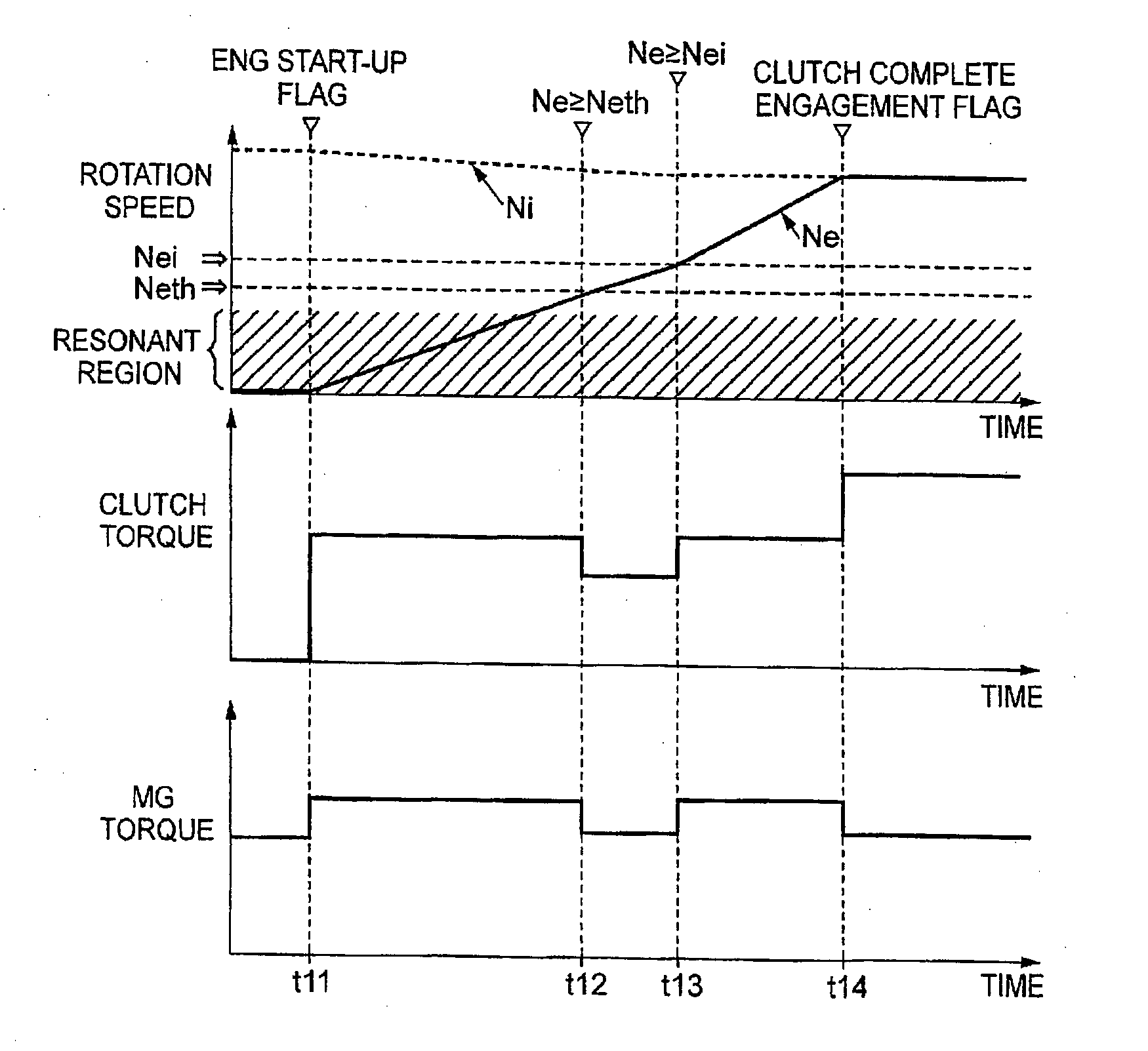
[0031]The invention provides a control system for a vehicle including an engine and a clutch. The engine starts up by cranking. The clutch transmits torque for the cranking to the engine via the clutch. The clutch is able to change its transmitted torque capacity. A motor for the cranking may be a so-called starter motor or may be a motor (or a motor generator; hereinafter, these are collectively referred to as motor) that generates driving force for propelling the vehicle. The vehicle including the motor as a driving force source in addition to the engine is called hybrid vehicle. This kind of vehicle is able to not only travel by using the engine or travel by using both the engine and the motor but also, for example, travel by using only the motor or travel while carrying out energy regeneration with the motor. The hybrid vehicle is able to be set to a drive mode in which, for example, the engine is stopped while the vehicle is traveling by using the motor and then the engine is r...


PUM


Abstract

In a control system and a control method, an electronic control unit is configured to crank an engine by setting a clutch to a half engaged state in a state where operation of the engine is stopped during traveling. The half engaged state is a state where the clutch is engaged with a slip. The electronic control unit is configured to, after a rotation speed of the engine has reached an ignition permission rotation speed or higher, increase a transmitted torque capacity of the clutch to a transmitted torque capacity that satisfies the following conditions i) and ii): i) the transmitted torque capacity is larger than a transmitted torque capacity before the rotation speed of the engine has reached the ignition permission rotation speed; and ii) the transmitted torque capacity allows the clutch to be kept in the half engaged state.

Description

BACKGROUND OF THE INVENTION[0001]1. Field of the Invention[0002]The invention relates to a control system and control method for a vehicle equipped with an engine that is started up by cranking (or motoring) and, more particularly, to a control system and control method that control a clutch that is engaged to start up the engine and a motor for cranking.[0003]2. Description of Related Art[0004]An internal combustion engine, such as a gasoline engine and a diesel engine, which is used as a driving force source of a vehicle autonomously rotates by igniting fuel that is supplied in a state where the rotation speed is increased to a predetermined rotation speed. A vehicle that uses only an internal combustion engine as a driving force source needs such so-called start-up control. Therefore, the vehicle that uses only the internal combustion engine as the driving force source keeps the engine in an idling state even when the vehicle is stopped. However, idling during a stop of the vehic...

Claims


Application Information

Patent Timeline
Patent Type & Authority Applications(United States)
IPC IPC(8): B60W20/10B60W10/06B60W10/08B60K6/54F16H37/08B60K6/442B60K6/387F16H3/72B60W10/02
CPCB60K6/365F16D2500/7044B60K6/48B60W10/02B60W10/06B60W10/08B60W20/00B60W30/20F16D48/06B60W2510/0241B60W2510/0275B60W2510/0638B60W2710/027B60W20/40B60W30/18018F16D2500/70282F16D2500/3067F16D2500/50227F16D2500/70252F16D2500/7041F16D2500/70426Y02T10/6221Y02T10/6286Y02T10/6239B60W2720/30B60W2710/083B60W2710/025B60W2710/021B60W20/10B60K6/54Y10S903/93B60K6/387F16H37/0833F16H3/728F16H3/725B60Y2300/182B60Y2200/92B60K6/442B60K6/445B60W30/192B60W2030/206Y02T10/62
Inventor HATA, KENSEIFUNAHASHI, MAKOTOIWASE, YUJISUZUKI, YOSUKENOBUYASU, SEITAROWATANABE, KOICHIOYA, SHOJIROOSHIRO, YUTA
Owner TOYOTA JIDOSHA KK
Why Eureka
Try Eureka