Efficient Flight Paths for Aerial Corridor Inspection

Inactive Publication Date: 2016-08-11
VAN CRUYNINGEN IZAK JAN
View PDF4 Cites 30 Cited by
  • Summary
  • Abstract
  • Description
  • Claims
  • Application Information

AI Technical Summary

Benefits of technology

The patent describes a flight path for an airframe with a camera that can inspect electrical transmission lines. The flight path is designed to be energy efficient and minimize blurring in the camera's exposures. When the power plant is off, the airframe vibrations are reduced, and the arcs around the towers help to stabilize the airframe. The drift in the inertial measurement unit can also be reset. This flight path can be used to detect insulator failure and enable precision flying during the return detailed inspection.

Problems solved by technology

Fuel is a major expense for most aircraft, so there has been a great deal of effort expended in developing energy efficient flight plans.
Most engines run much less efficiently when operated at a fraction of their maximum power.
Regulatory agencies limit their weight, speed, and / or the height above ground under which they may be used.
Efficient flight reduces the energy required to complete the mission and thus the battery weight.

Method used


Image

  • Efficient Flight Paths for Aerial Corridor Inspection
  • Efficient Flight Paths for Aerial Corridor Inspection
  • Efficient Flight Paths for Aerial Corridor Inspection

Examples


Embodiment Construction

[0024]This section describes several embodiments of the efficient corridor inspection flight path with reference to FIGS. 1-6.

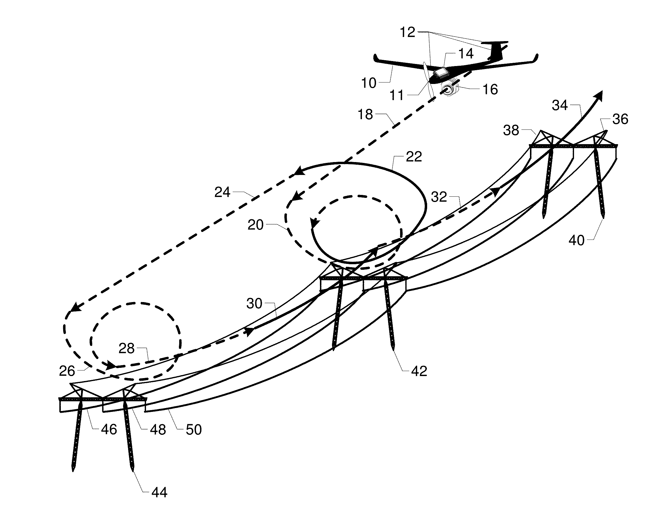
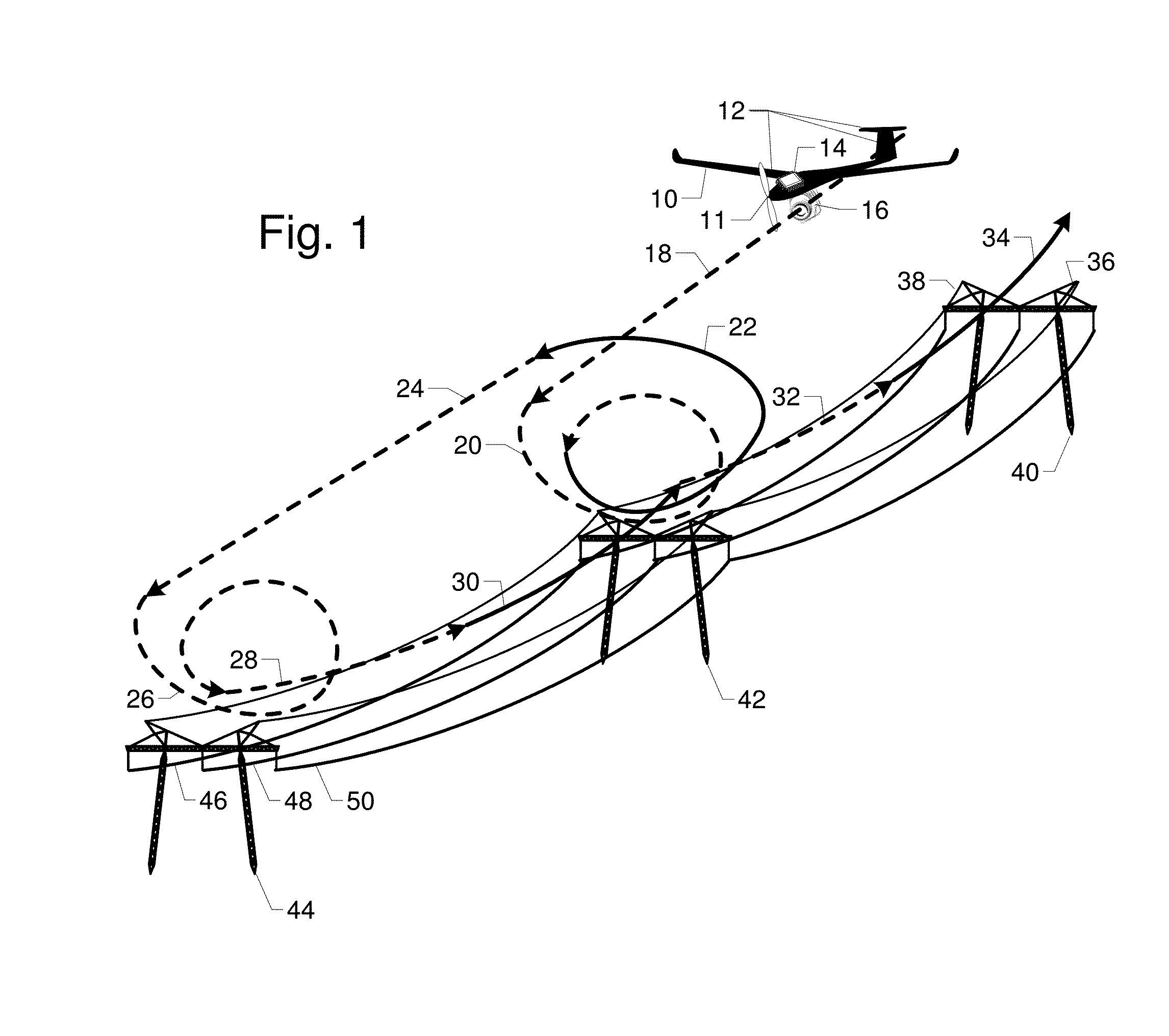
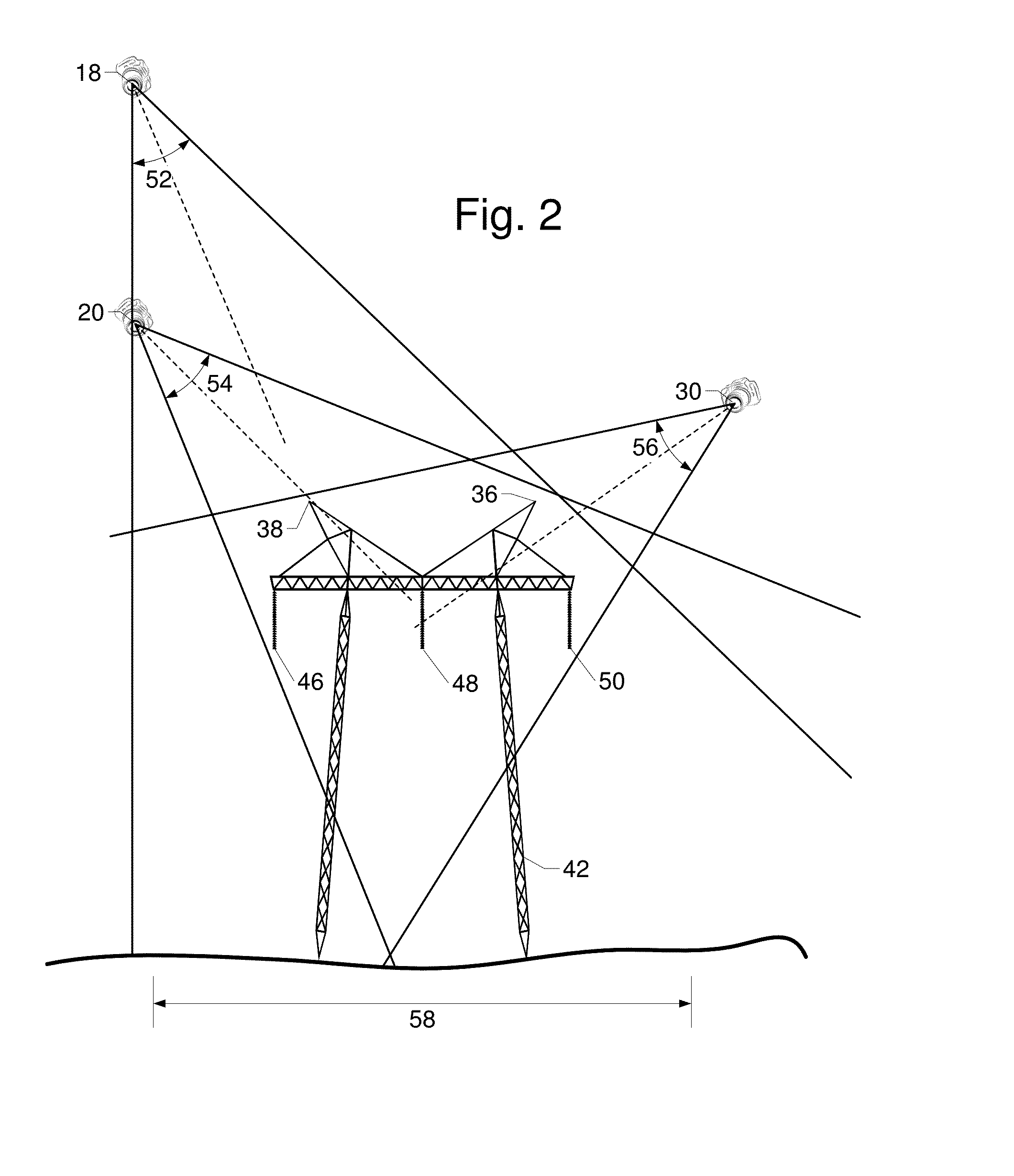
[0025]FIG. 1 is a perspective view of a utility corridor inspection flight path for power transmission lines. An aerial inspection system includes an airframe 10 that supports power plant 11, control surfaces 12, autopilot 14, and camera 16. Towers 40, 42, and 44 support phase conductors 46, 48, and 50, as well as shield wires 36 and 38. Airframe 10 inspects the corridor in a flight path combining linear right of way glide 18; followed by spiral tower glide 20 around tower 42; power climb 22; linear right of way glide 24; and spiral tower glide 26 around tower 44. On the return path airframe 10 does a close-in conductor inspection by flying catenary glides 28, 32 on the downslopes and catenary climb 30, 34 on the upslopes.

[0026]This example is for a single circuit 500 kV transmission line where towers 40, 42, and 44 are ˜40 m high, ˜25 m wide, and spaced 200-...


PUM


Abstract

FIG. 1 shows an efficient flight path for airframe 10 with camera 16 flying along a transmission line utility corridor containing towers 40, 42, and 44. Between the towers the airframe is in a fast linear glide 18 to check the right of way for encroachment. Abreast of tower 42, the airframe spirals down 20 with power plant 11 off to take more detailed pictures. When the tower inspection is complete, power plant 11 is turned on to start a power climb 22 back up to prepare for glide 24 to the next tower 44, where the airframe again spirals down 26 for a closer inspection. On the return flight, a close-in conductor inspection is flown in catenary arcs with glides 28, 32 on the downslope and power climb 30, 34 on the upslope.

Description

CROSS-REFERENCE TO RELATED APPLICATIONS[0001]This application claims the benefit of provisional patent application Ser. No. 61 / 937,048 filed 2014 Feb. 7 by the present inventor.BACKGROUND—PRIOR ART[0002]Fuel is a major expense for most aircraft, so there has been a great deal of effort expended in developing energy efficient flight plans. A power plant large enough for take-off and climbing flight, is two to four times larger than needed for level flight. Most engines run much less efficiently when operated at a fraction of their maximum power. Transmissions are used to correct this mismatch in terrestrial vehicles.[0003]Soaring gliders provide the best energy efficiency for experienced pilots since they use energy in thermals to stay aloft. Touring motor gliders provide energy efficient cross-country flight without reliance on thermals. However, they must plan for a landing site just in case the engine does not restart. They have a minimum safe height above ground.[0004]Unmanned ae...

Claims


Application Information

Patent Timeline
IPC IPC(8): B64C31/024B64C39/02G08G5/00B64D47/08
CPCB64C31/024B64D47/08B64C39/024G08G5/0069B64C2201/162G08G5/0086B64C2201/021B64C2201/127G08G5/0034G05D1/0005G05D1/0094B64C13/18B64U2101/30B64U2201/10B64U10/25
Inventor VAN CRUYNINGEN, IZAK JAN
Owner VAN CRUYNINGEN IZAK JAN
Why Eureka
Try Eureka