Device and method for determining a state of an object which is to be monitored

a technology for determining the state of an object and a method, applied in the direction of acceleration measurement in multiple dimensions, acceleration measurement using interia forces, instruments, etc., can solve the problems of limited implementation, the possibility of state transition from a current state to a new state, etc., and achieve reliable determination of state changes. , the effect of convenient forwarding

Active Publication Date: 2016-08-11
ROBERT BOSCH GMBH
View PDF4 Cites 9 Cited by
  • Summary
  • Abstract
  • Description
  • Claims
  • Application Information

AI Technical Summary

Benefits of technology

[0016]In a specific embodiment, the communication interface wirelessly transmits the state determined by the processing device. Such a wireless data transmission enables a very convenient forwarding of the ascertained state data, in particular in the case of movable objects.
[0017]In a specific embodiment, the magnetometer and / or the acceleration sensor can be deactivated by the processing device. In this way, for example a state change of the object can at first be monitored by only one sensor. As soon as this one sensor detects a possible state change, the processing device can thereupon also activate the further sensor. In this way, on the one hand a particularly energy-saving monitoring of the object is possible, while at the same time, through the activation of additional sensors on an as-needed basis, a reliable determination of state changes can be carried out.

Problems solved by technology

In addition, for the determination of a new state of the object the possibility of the state transitions from a current state to a new state can also be defined and limited.

Method used


Image

  • Device and method for determining a state of an object which is to be monitored
  • Device and method for determining a state of an object which is to be monitored
  • Device and method for determining a state of an object which is to be monitored

Examples


Embodiment Construction

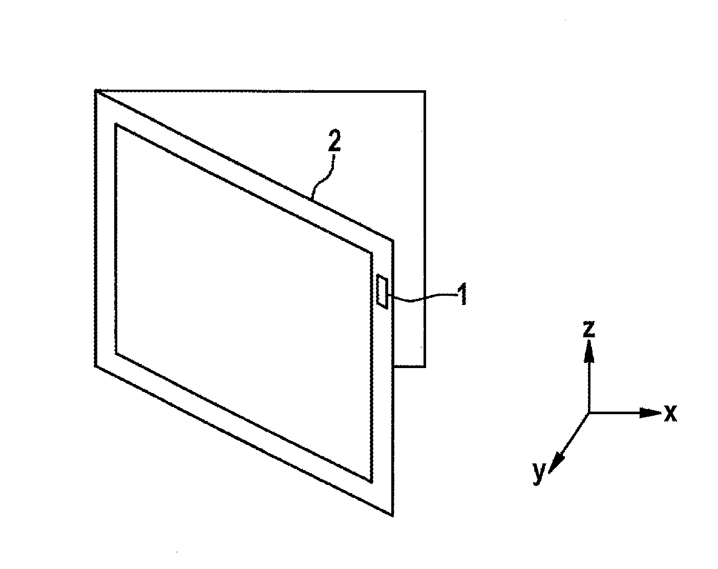
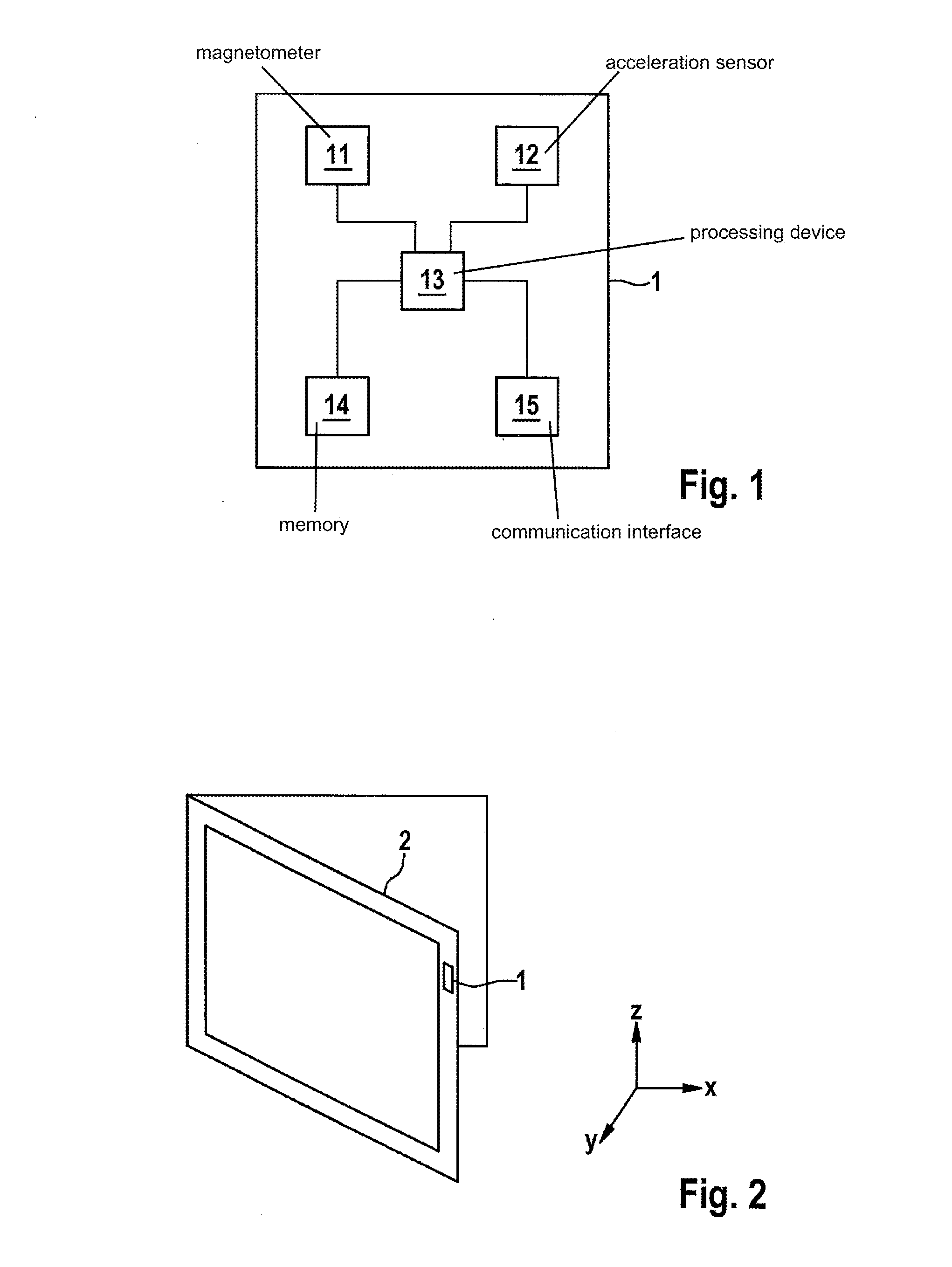
[0026]FIG. 1 shows a schematic representation of a block diagram of a device 1 for ascertaining a state of an object to be monitored according to a specific embodiment. Device 1 includes a magnetometer 11 and an acceleration sensor 12 that are connected to a processing device 13. This processing device 13 is further connected to a memory 14 and to a communication interface 15.

[0027]Magnetometer 11 is preferably a three-axis magnetometer. Such a magnetometer acquires a magnetic field in all three spatial directions. In particular, such a magnetometer is capable of separately detecting changes in the magnetic field in one or more spatial directions. Magnetometer 11 forwards its measurement results to processing device 13 in the form of measurement signals.

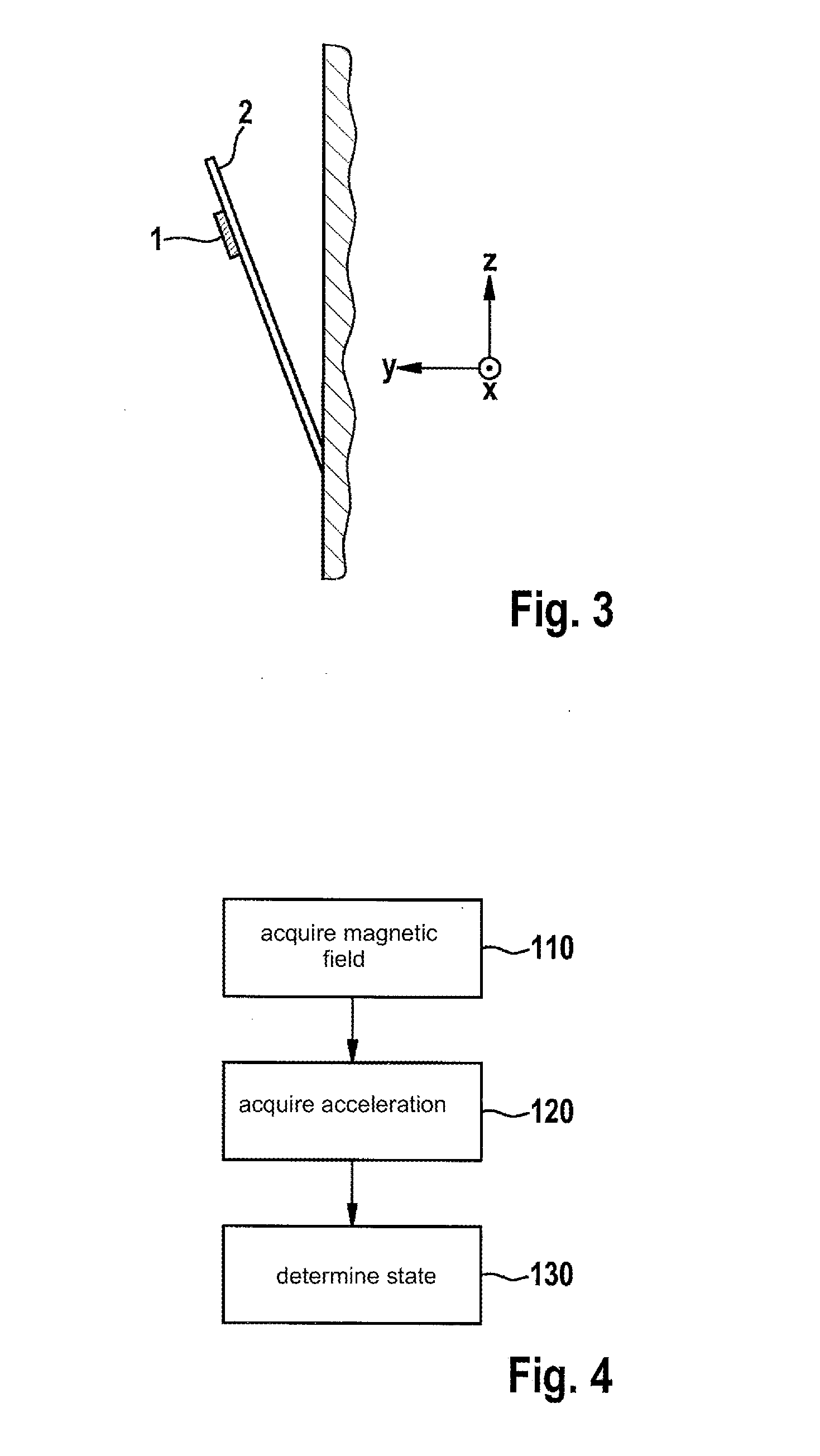
[0028]Through continuous monitoring of a static magnetic field, such as the Earth's magnetic field, magnetometer 11 can thus recognize a movement of magnetometer 11 within this magnetic field.

[0029]Acceleration sensor 12 is likewise ...


PUM


Abstract

A device and a method for determining states of an object to be monitored, such as a window or a door. The measurement values of a plurality of sensors, in particular a magnetometer and an acceleration sensor, are merged and are evaluated together. For the determination of a new state from a group of predefined states, only state transitions that are actually possible are taken into account. State transitions that are not possible or are not allowed are not taken into account.

Description

FIELD[0001]The present invention relates to a device and to a method for determining a state of an object that is to be monitored.BACKGROUND INFORMATION[0002]Sensors for monitoring states of doors and windows are conventional. Generally, these conventional sensors are realized in two parts. A first part of the sensor is made up of a permanent magnet. A second part of the sensor has a magnetic sensor, for example a reed contact, that can be opened or closed by the permanent magnet in the first part of the sensor. Here, a part of the sensor has to be attached to the movable frame of the window or door that is to be monitored, and the other part of the sensor has to be fastened outside the movable frame, for example on the wall. If the door or window is closed, then the reed contact is triggered by the magnetic field of the permanent magnet. If the door or the window is open, the reed contact is not triggered.[0003]German Patent Application No. DE 103 35 126 A1 describes a device for s...

Claims


Application Information

Patent Timeline
Patent Type & Authority Applications(United States)
IPC IPC(8): G01P13/00G01R33/02G01P1/07G01D5/14G01P15/18
CPCG08B13/08G01D5/14G01R33/0206G01P13/00G01P15/18G01P1/07G08B13/24G08B25/10G08B25/14
Inventor SCHEIERMANN, SERGEJKAACK, ROLF
Owner ROBERT BOSCH GMBH
Why Eureka
Try Eureka