Rotary mill

a rotary mill and milling machine technology, applied in the field of rotary mills, can solve the problems of post-operative pain, damage to bearings, and more design requirements for partial knee replacement prostheses than those for total knee replacement prostheses, and achieve the effect of avoiding excessive bone removal and precise bone removal

Inactive Publication Date: 2016-08-18
BIOMET UK HEALTHCARE
View PDF1 Cites 2 Cited by
  • Summary
  • Abstract
  • Description
  • Claims
  • Application Information

AI Technical Summary

Benefits of technology

[0010]The arm may be provided with a recess on a first side which is adapted to accommodate the milling surface without impingement. An opposite side of the arm may be polished chamfered or otherwise shaped such that it does not damage the second bone.
[0011]The guide body may include at least one nodule, protruding from a surface of the guide body and operable to abut a corresponding abutment surface on the body portion. The nodules may thus act as depth stops to ensure a precise amount of bone is removed and avoid excessive bone removal.
[0015]The guide body may be operable to be connected to additional surgical tools, thus facilitating and providing reference for additional bone removal steps.

Problems solved by technology

However, the design requirements for partial knee replacement prostheses are more demanding than those for total knee replacement prostheses.
Such impingement of the polyethylene bearing component onto the bone can lead to post operative pain, damage to the bearing, increased wear and eventual failure.
If the leg is insufficiently flexed or the anatomy of the patient is such that the tibia projects more than is normal, it is possible that the rotary could contact tibia, during milling of the femoral condyle, thereby causing undesirable milling of the surface of the tibia.

Method used


Image

  • Rotary mill
  • Rotary mill
  • Rotary mill

Examples


Embodiment Construction

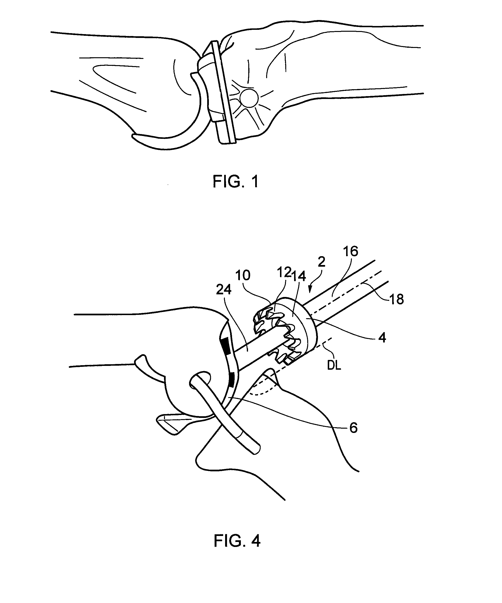
[0032]FIGS. 1 to 11 illustrate the use of a rotary mill having a standard guide portion, whereas FIG. 12 illustrates a modified guide portion having a cutting guard in accordance with the present invention.

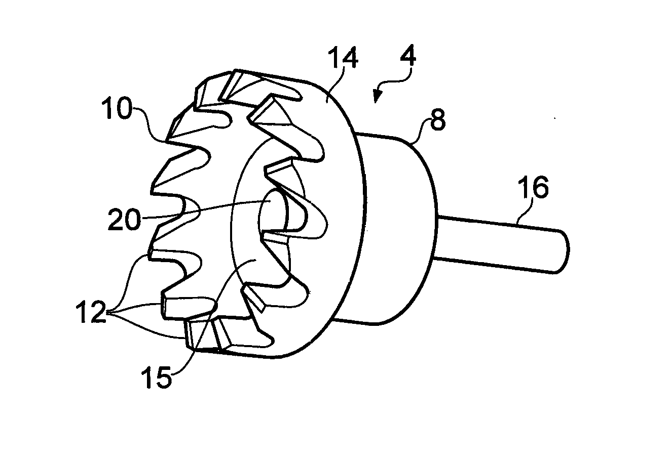
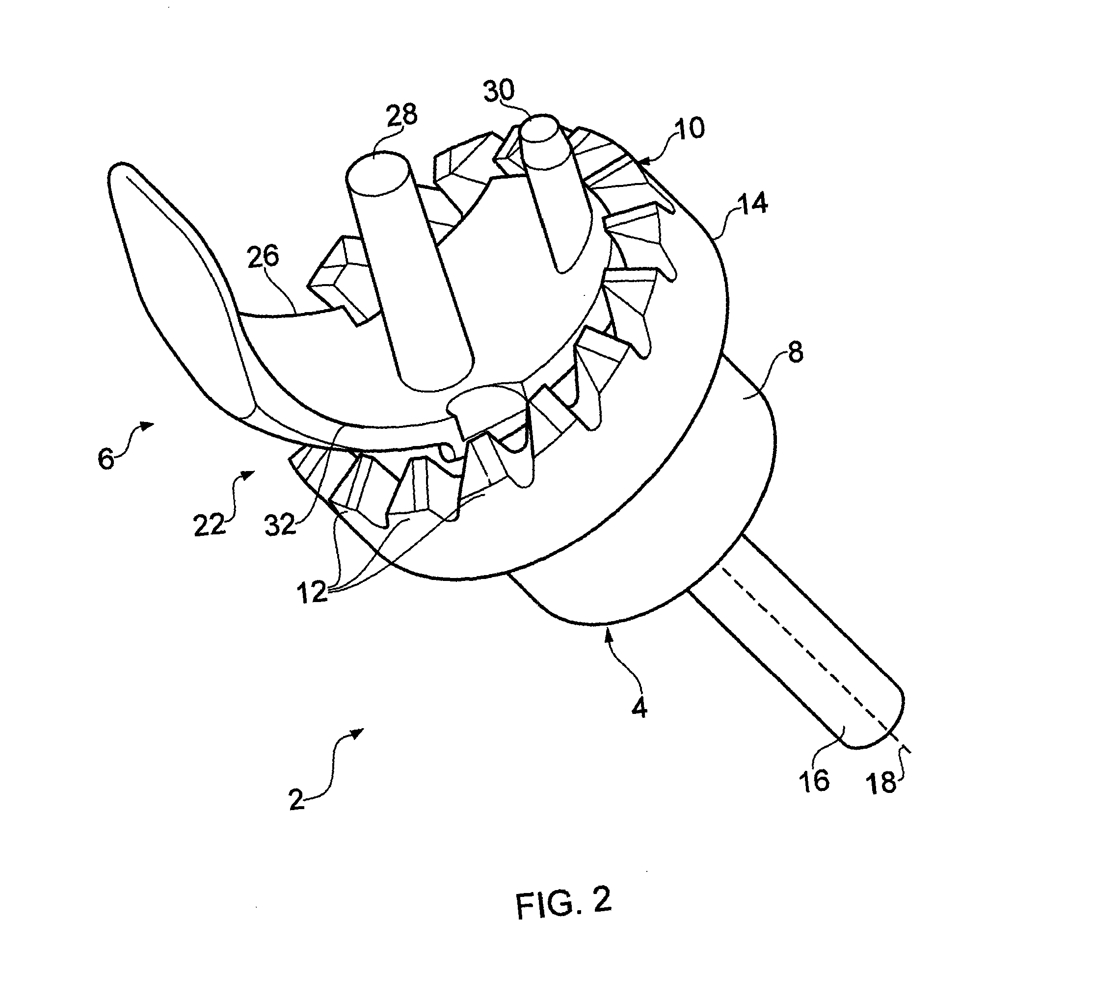
[0033]With reference to FIG. 2, a rotary mill 2 comprises a body portion 4 and a guide portion 6. The body portion 4 comprises a rotary body 8 that terminates at one end in an annular milling surface 10. The milling surface comprises a series of milling teeth 12 that extend from the surface 10. In the illustrated embodiment, the milling surface 10 is formed on an annular shoulder 14 that protrudes outwardly from the rotary body 8. An abutment surface 15 extends radially inwardly of the projecting milling surface 10. At a second end of the rotary body 8 an integral shank 16 extends along an axis of rotation 18 of the rotary body. The shank 16 is suitable for attachment to the chuck of a surgical drill (not shown). A bore 20 extends through the rotary body 8 along the axis of rotati...


PUM


Abstract

A rotary mill (2) comprising a body portion (4) having a milling surface (10) for milling a first bone, a guide portion (6) having a guide body (22), and inter-engageable guide formations (20, 24) formed on the body portion (4) and guide portion (6), the guide body (22) having a projection (7) which is adapted to hold a second bone (11) away from the rotary mill during the milling operation.

Description

[0001]The present invention relates to rotary mills and similar rotary cutting devices and particularly but not exclusively relates to rotary mills for use in preparing a bone for total or partial joint replacement surgery.BACKGROUND[0002]It is known to replace all or part of a knee joint in which the joint surfaces have deteriorated, for example as a result of osteoarthritis. Such deterioration usually starts in only one of the tibeo-femoral compartments and may spread to the other at a later stage. Replacement of only one compartment of the joint can therefore be sufficient to provide prolonged relief from symptoms. Damaged bearing surfaces are replaced by a unicompartmental prosthesis which comprises a femoral implant and a tibial implant (usually metallic), which interface through a (polyethylene) bearing component disposed between the two implants.[0003]A unicompartmental or partial knee replacement (PKR) helps to conserve undamaged bone and restores more natural movement to th...

Claims


Application Information

Patent Timeline
Patent Type & Authority Applications(United States)
IPC IPC(8): A61B17/16A61B17/17
CPCA61B17/1675A61B17/1764A61B17/17A61B17/16A61B2017/1602
Inventor RIDLEY, DUNCAN ANDREWALINEJAD, MONALLOYD, RUSSELLMURRAY, DAVID WYCLIFFEDODD, CHRISTOPHER
Owner BIOMET UK HEALTHCARE
Why Eureka
Try Eureka