
Low mass chain link and assembly for friction reduction

Inactive Publication Date: 2016-08-18
BORGWARNER INC
View PDF0 Cites 4 Cited by
  • Summary
  • Abstract
  • Description
  • Claims
  • Application Information

AI Technical Summary

Benefits of technology

The patent text describes a design for a chain wheel that reduces mass and improves efficiency in a system. This is achieved by adding a cavity to the opposite side of the contact surface, which eliminates unnecessary material from the chain. This design reduces manufacturing costs and complexity and makes the chain more efficient in its movement. Other design features like concave edges and holes can further improve system efficiency.

Problems solved by technology

This frictional loss results in lower fuel efficiency when used as an engine timing drive or auxiliary drive within an automotive engine.

Method used


Image

  • Low mass chain link and assembly for friction reduction
  • Low mass chain link and assembly for friction reduction
  • Low mass chain link and assembly for friction reduction

Examples


Embodiment Construction

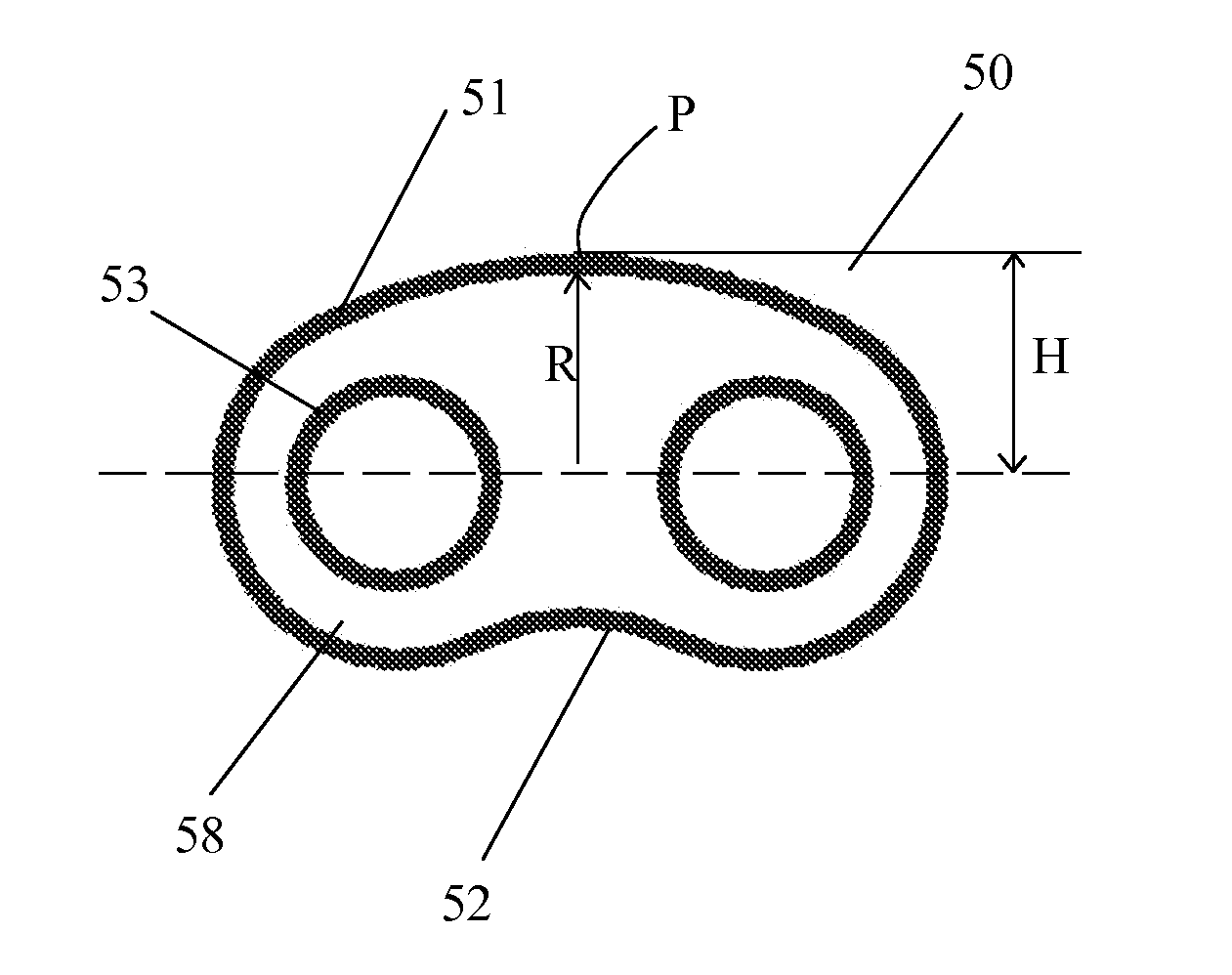
[0039]The current invention includes a link plate design that incorporates an optimized edge profile shape and link mass reduction.

[0040]FIG. 5A illustrates an internal link plate 50 with a body 58 which would contain bushings 11 pressed into the link plate apertures or bushing holes 53. The holes may also contain connecting pins (not shown). The internal link plate 50 has a convex back edge 51 for sliding contact with a guide 6 or a tensioner arm 4 as depicted in FIG. 13. The convex back edge 51 has a profile in which at least a portion contacts the sliding surfaces 4a, 6a of arms 4 and guides 6 within an engine timing drive, oil pump drive, or any other auxiliary drive. The profile of the convex back edge 51 is comprised of an arc with a radius R, such that a high point of the profile, formed by the radius R, contacts the sliding surfaces 4a, 6a of the arms 4 and guides 6. The radius R is preferably optimized for friction reduction. By having a back edge 51 with a convex profile w...


PUM


Abstract

Roller chain links, both internal and external which include a link outer profile that contains at least one convex back edge. In an alternate embodiment, the link also contains a concave back edge. Additionally, the links may contain an extra hole or window within the link profile combined with the convex and concave edge profiles for additional mass reduction.

Description

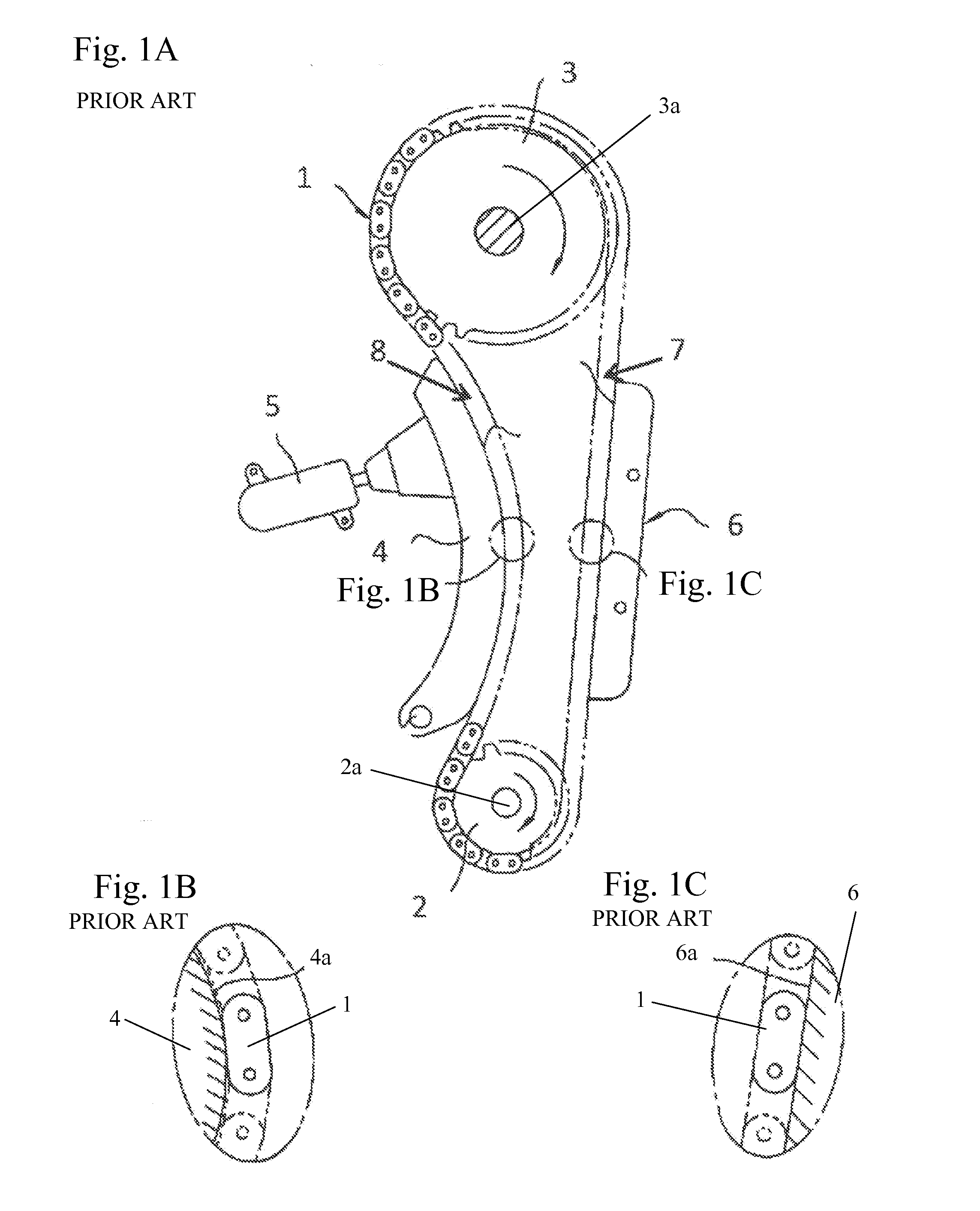
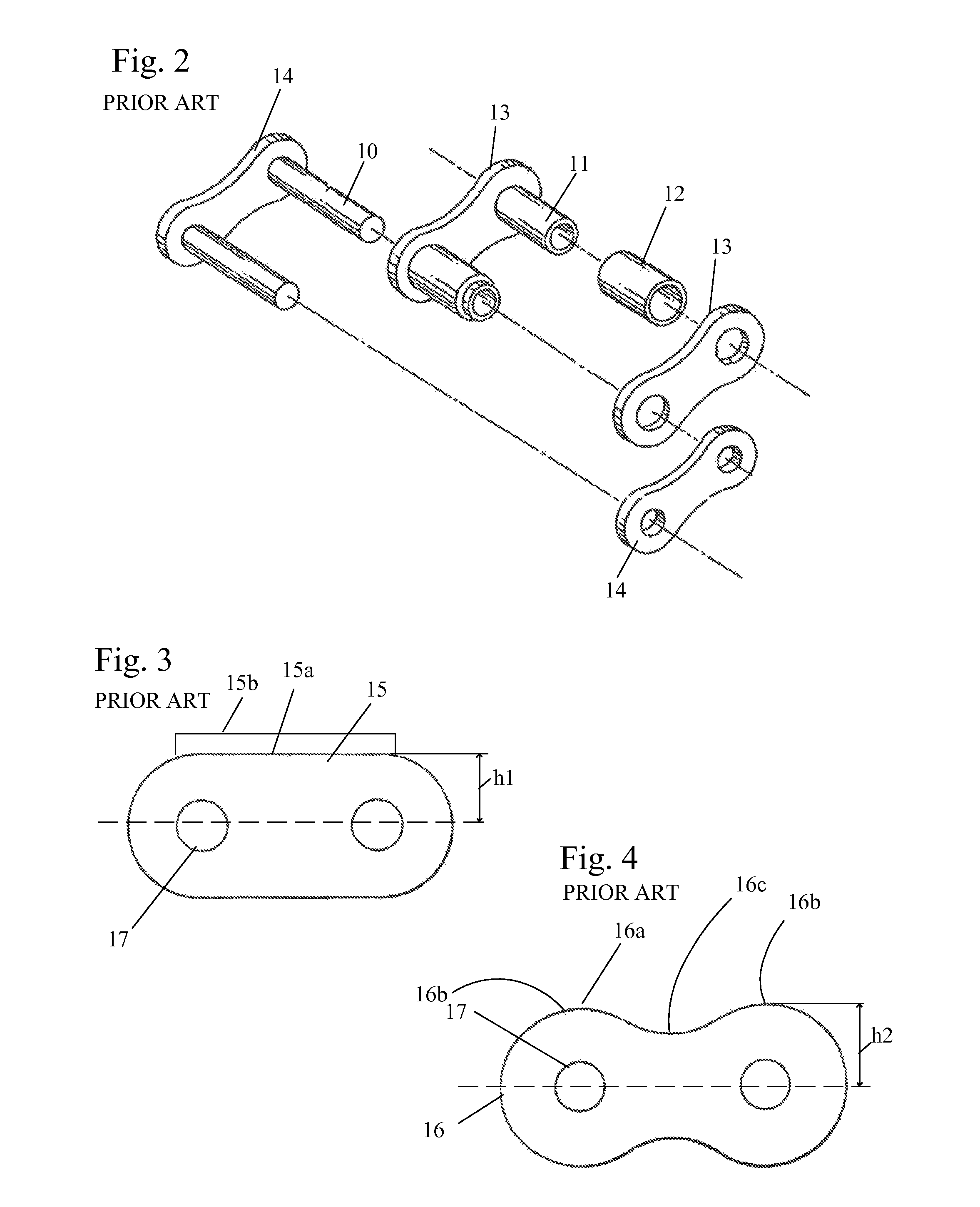
BACKGROUND OF THE INVENTION[0001]1. Field of the Invention[0002]The invention pertains to the field of chain links More particularly, the invention pertains to low mass chain links assembled into a chain for friction reduction.[0003]2. Description of Related Art[0004]In a typical engine timing drive, which may include the primary drive, secondary cam drive, and oil pump drive, a chain can be used to transmit power from one sprocket and shaft to another and allow synchronized rotation between the shafts.[0005]FIG. 1A shows a typical engine timing drive layout consisting of a chain 1, crankshaft sprocket 2, camshaft sprocket 3, tensioner arm 4, tensioning device 5, and guide 6. Power from the crankshaft sprocket 2 is transmitted to the camshaft sprocket 3 through a flexible chain 1, which allows synchronous rotation between the crankshaft 2a and camshaft 3a, which is essential to maintaining engine timing.[0006]As a torque is applied to crankshaft sprocket 2, a resistant torque is app...

Claims


Application Information

Patent Timeline
IPC IPC(8): F16G13/06
CPCF16H7/06F16H7/08F16H7/18F16G13/06F16H2007/0872F16H2007/0893F16H9/24
Inventor VROMAN, SHAWN R.MAXSON, TIMOTHY J.
Owner BORGWARNER INC
Learn More