Hair dryer with air outlet arrangement

a dryer and air outlet technology, applied in the field of hair dryers, can solve the problems of hair damage, hair damage, actual burning,

Inactive Publication Date: 2016-08-25
KONINKLJIJKE PHILIPS NV
View PDF5 Cites 8 Cited by
  • Summary
  • Abstract
  • Description
  • Claims
  • Application Information

AI Technical Summary

Benefits of technology

[0006]It is an object of the present invention to provide a hair dryer that mitigates an overheating of hair and having a reduced complexity and cost. The invention is defined by the independent claims. The dependent claims define advantageous embodiments.
[0013]According to a variant of this embodiment above a pressure threshold and / or a temperature threshold the effective cross section is automatically increased. If an obstacle (partially) blocks an opening of the air outlet arrangement, the air flow that can exit the air outlet arrangement is reduced. The decreased air flow corresponds to a lower air mass per unit time which passes the heating element. In consequence, the lower air mass is heated up to a higher temperature. To prevent damaging the hair, the air outlet area of the air outlet arrangement is increased above a temperature threshold of, for example, 100° C. Experiment of the applicant have shown that thermal damages of the hair may already occur at a temperature of 100° C. At higher temperatures up to 200° C. heavy burnings of the hair and the scalp can be caused.
[0015]An air outlet arrangement with a nozzle typically has a limited effective cross section during normal operation in order to ensure a fast, powerful stream of air. When styling hairs with a brush, a user may come too close to the hair with the nozzle and block a substantial part of the cross section. In consequence the air flow that exits the housing through the air outlet arrangement reduces even more. As explained above, the reduced amount of air that now passes the heating element is heated up to a higher temperature. Furthermore, the pressure within the housing increases as the obstacle increases the resistance for the flow of air. In the present embodiment, the flow changing device of the air outlet arrangement change the flow of air that exits the outlet arrangement by increasing the effective cross section of the air outlet arrangement. In consequence, the flow of air increases. As the effective cross section of the air outlet arrangement is increased, the flow of air is not limited to exiting the air outlet arrangement through a narrow space besides the obstacle (e.g. a brush) but has a pathway of larger effective cross section. The heating power of the heating element heats up the air mass that passes the heating element. As the flow of air and thus the air mass is increased, the air temperature is reduced.
[0018]According to another embodiment of the hair dryer according to the present invention, the flow changing device further comprises a spring element for exerting a closing force on the mechanical shutter that counteracts an opening force on the mechanical shutter, which opening force is caused by the pressure within the housing. In this particular embodiment, the flow changing device change a flow of air at the air outlet arrangement depending on a pressure within the housing. For example, if an obstacle (partially) blocks an opening of the air outlet arrangement, the pressure within the housing increases. The pressure within the housing causes an opening force that presses against the mechanical shutter. The spring element of the flow changing device exerts a closing force on the mechanical shutter that tries to close the mechanical shutter or hold the mechanical shutter closed against the opening force. When the opening force caused by the pressure within the housing exceeds the closing force, the mechanical shutter opens. As described above, an opening of the mechanical shutter can increase the effective cross section of the air outlet arrangement. Hence, the flow of air can (partially) pass through the airway that was opened by the shutter. As the flow of air exits the housing, the pressure within the housing decreases. When the closing force exceeds the opening force, the shutter has returned to its closed position. The pressure threshold when the shutter opens can be set by the spring constant of the spring element.
[0027]According to an alternative embodiment of the hair dryer according to the present invention, the heating element and / or the fan is configured such that an air temperature of the flow of air is limited to a maximum value, when the flow of air exits through the bypass air outlet only. Assuming that the main air outlet is completely blocked, the entire flow of air will exit through the bypass air outlet. Even in this extreme scenario, the air temperature does not cause damage to the hair or discomfort to the user. The power of the heating element and / or the fan speed is dimensioned such that even when the entire flow of air exits through the bypass air outlet only, an overheating is prevented. A bypass air outlet with large effective area will allow a higher maximum heating power.

Problems solved by technology

At high temperatures, the hair can be damaged and / or a burning sensation may arise, which may even lead to actual burning.
The problem is to achieve fast drying without damaging the hair.
If they get too close, for example less than 2 cm, the hair may be (partly) shutting off the air outlet area which reduces the air flow significantly.
The resistance can cause a reduction of the rotation speed of the fan and decrease the air flow.
The air temperature can increase up to potentially dangerous, hair damaging values.
However, the solution proposed in U.S. Pat. No. 5,790,749 involves additional effort for sensing and control circuitry.
This leads to a high complexity of today's hair dryers and increases the overall costs.

Method used


Image

  • Hair dryer with air outlet arrangement
  • Hair dryer with air outlet arrangement
  • Hair dryer with air outlet arrangement

Examples


Embodiment Construction

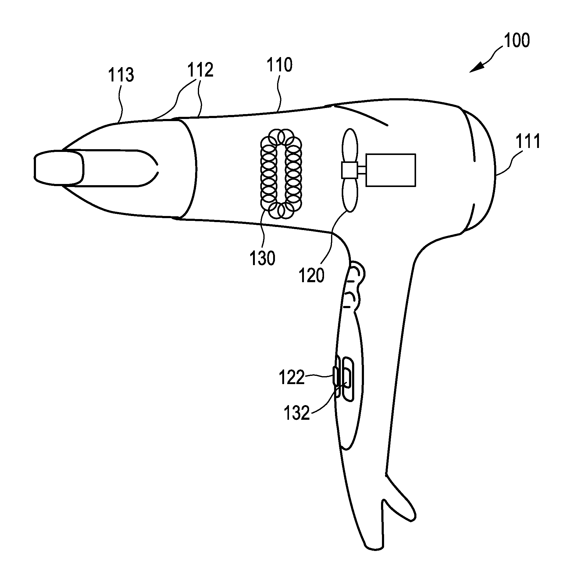
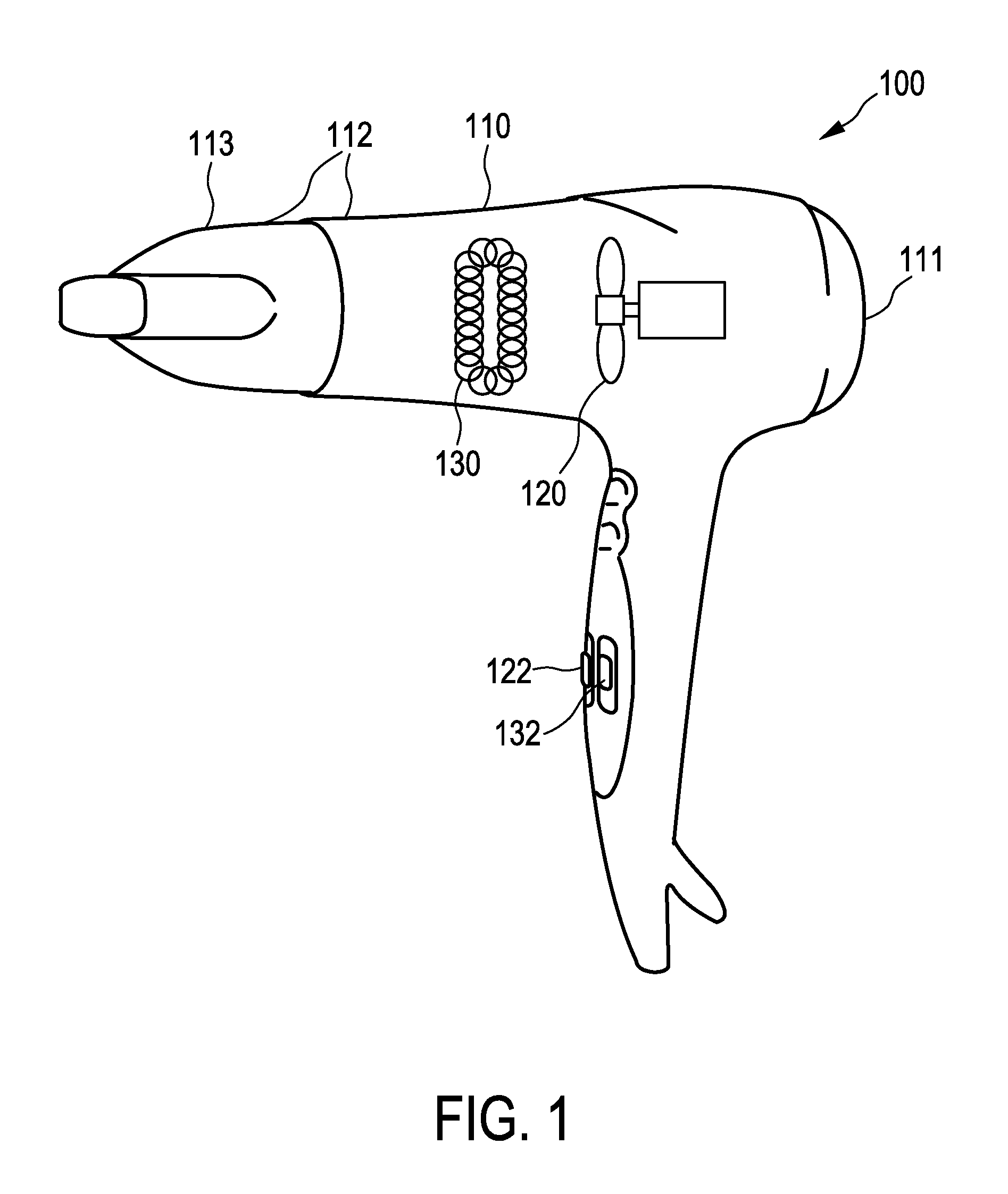
[0039]FIG. 1 shows an electrical hair dryer 100 comprising a housing 110 with an air inlet 111 and an air outlet arrangement 112. In this particular embodiment the air outlet arrangement 112 also features a nozzle 113. The nozzle 113 is optional. In the housing 110 there are a fan 120 and a heating element 130. The fan 120 generates a flow of air from the air inlet 111 to the air outlet arrangement 112. Any type of air flow generating device can be used as a fan. The heating element 130 heats the flow of air. Different types of heating elements are available for example coils of wire with high electric resistivity such as nichrome wires, infrared heaters and ceramic heating elements. The fan speed is controlled via a fan control switch 122 that allows to set the fan speed. The heating power of the heating element 130 is controlled via a heat control button 132. In this embodiment it is possible to control fan speed and heating power independently from each other. However, in a diffe...


PUM


Abstract

The present invention relates to a hair dryer (100) and a nozzle (113, 310, 410) for a hair dryer (100), and more specifically to an air outlet arrangement (112, 220, 300, 400, 500, 600, 700). The air outlet arrangement (112, 220, 300, 400, 500, 600, 700) comprises a flow changing device (223, 224, 331, 341, 431, 531, 631, 632) for changing a flow of air at the air outlet arrangement (112, 220, 300, 400, 500, 600, 700), depending on a pressure and / or temperature within a housing (110), in particular within the nozzle (113, 310, 410).

Description

FIELD OF THE INVENTION[0001]The present invention relates to the field of hair dryers, and more specifically to an air outlet arrangement.BACKGROUND OF THE INVENTION[0002]A hair dryer is a device for drying hair by blowing heated air over the hair in order to accelerate the evaporation of water. An electrical hair dryer typically comprises a housing with an air inlet and an air outlet, a fan for generating a flow of air from the air inlet to the air outlet and a heating element for heating the flow of air. Nozzles, also referred to as concentrators, are optionally positioned at the air outlet, for example to increase the air speed for styling purposes. The user of a hair dryer with attached nozzle has the impression that the dryer is more “powerful” than without nozzle.[0003]For quick drying, a strong heating power is desirable. At the beginning of the evaporation process, the water held by the hair forms a thermal screen which prevents deterioration or burning of the hair or the sc...

Claims


Application Information

Patent Timeline
Patent Type & Authority Applications(United States)
IPC IPC(8): A45D20/12
CPCA45D20/12A45D20/124A45D20/122A45D20/10
Inventor FLOESSHOLZER, HANNES UWE
Owner KONINKLJIJKE PHILIPS NV
Why Eureka
Try Eureka