
Fiber substrate stacking method, manufacturing method of roll of fiber substrate group, fiber substrate group, and aircraft

a technology of fiber substrate and manufacturing method, which is applied in the direction of layered products, chemistry apparatus and processes, and other domestic articles, etc., can solve the problems of resin impregnation property deterioration

Active Publication Date: 2016-08-25
MITSUBISHI AIRCRAFT
View PDF1 Cites 2 Cited by
  • Summary
  • Abstract
  • Description
  • Claims
  • Application Information

AI Technical Summary

Benefits of technology

The present invention describes a method of integrating fiber substrates with aligned border zones between their fiber bundles, which allows for a more effective resin impregnation of the fiber substrates. This results in a fiber-reinforced resin molded article with improved characteristics. The method also allows for greater design flexibility and facilitates the manufacture of parts by separate production of a fabric of fiber substrates with integrated borders. The information provided in the patent text can help to improve the manufacturing process for fiber-reinforced resin molded articles.

Problems solved by technology

However, the impregnation property of the resin deteriorates when the fiber substrates with their fiber bundles oriented in the same direction are successively stacked.

Method used

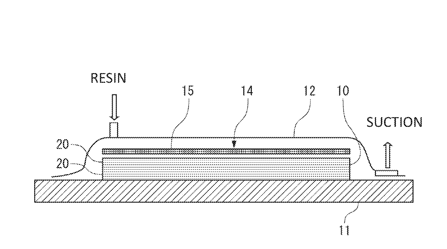

Image

  • Fiber substrate stacking method, manufacturing method of roll of fiber substrate group, fiber substrate group, and aircraft
  • Fiber substrate stacking method, manufacturing method of roll of fiber substrate group, fiber substrate group, and aircraft
  • Fiber substrate stacking method, manufacturing method of roll of fiber substrate group, fiber substrate group, and aircraft

Examples


first embodiment

Modified Example of First Embodiment

[0095]To integrate the fiber substrates 20 in each of the fiber substrate groups G1, G2, a thermoplastic non-woven fabric 26 shown in FIG. 5 or a coarse fabric can be used instead of the thermoplastic powder 24.

[0096]The non-woven fabric 26 is disposed between the fiber substrates 20 which are successively stacked with their fiber bundles 21 oriented in the same direction.

[0097]The non-woven fabric 26 is a tangle of fibers shaped into a sheet, and allows passage of the resin in the stack direction and the in-plane directions through clearances among the fibers. The non-woven fabric 26 presents a lower flow resistance to the matrix resin than the fiber bundles 21.

[0098]For example, the thermoplastic resins given above as examples of the thermoplastic powder 24 can be used as the material of the non-woven fabric 26.

[0099]Plasticizing the non-woven fabric 26 by heating can bond together the fiber substrates 20 through the non-woven fabric 26. Even af...

second embodiment

[0101]Next, a second embodiment of the present invention will be described with reference to FIG. 6.

[0102]Those components that are the same as in the first embodiment are given the same reference signs.

[0103]In the second embodiment, the auxiliary fibers 27 are used to integrate the fiber substrates 20 which are successively stacked with their fiber bundles 21 oriented in the same direction.

[0104]As shown in FIG. 6A, the fiber substrates 201 to 203 constituting the fiber substrate group G1 are stitched together along the array direction of the fiber bundles by the auxiliary fibers 27 which are passed between the adjacent fiber bundles 21, 21.

[0105]The auxiliary fiber 27 is composed of an auxiliary fiber 27A and an auxiliary fiber 27B which are alternately passed in the thickness direction between the fiber substrate 201 located on one surface side of the fiber substrate group G1 and the fiber substrate 203 located on the other surface side of the fiber substrate group G1.

[0106]The ...


PUM

PropertyMeasurementUnit
Lengthaaaaaaaaaa
Thicknessaaaaaaaaaa
Electrical resistanceaaaaaaaaaa

Abstract

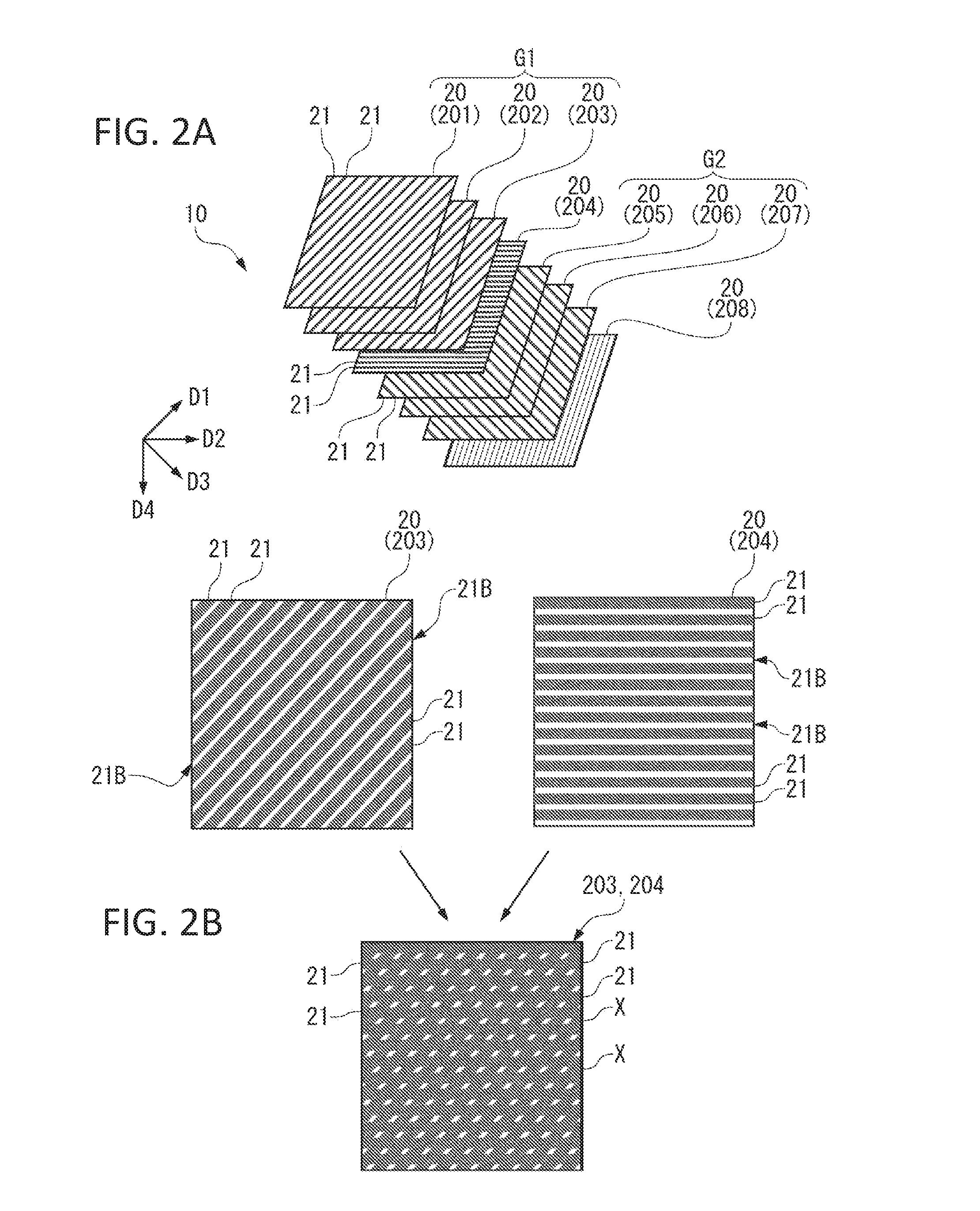
The present invention aims to sufficiently impregnate each layer of a fiber substrate group composed of fiber substrates, which are used for fiber-reinforced resin molding by a resin injection method, with a resin. To successively stack a plurality of fiber substrates, each of which has arrayed fiber bundles and is a material composing a fiber-reinforced resin along with a resin, with their fiber bundles oriented in the same direction, the plurality of fiber substrates are integrated in a state where border zones between the fiber bundles adjacent to each other in an array direction are aligned with one another among the fiber substrates.

Description

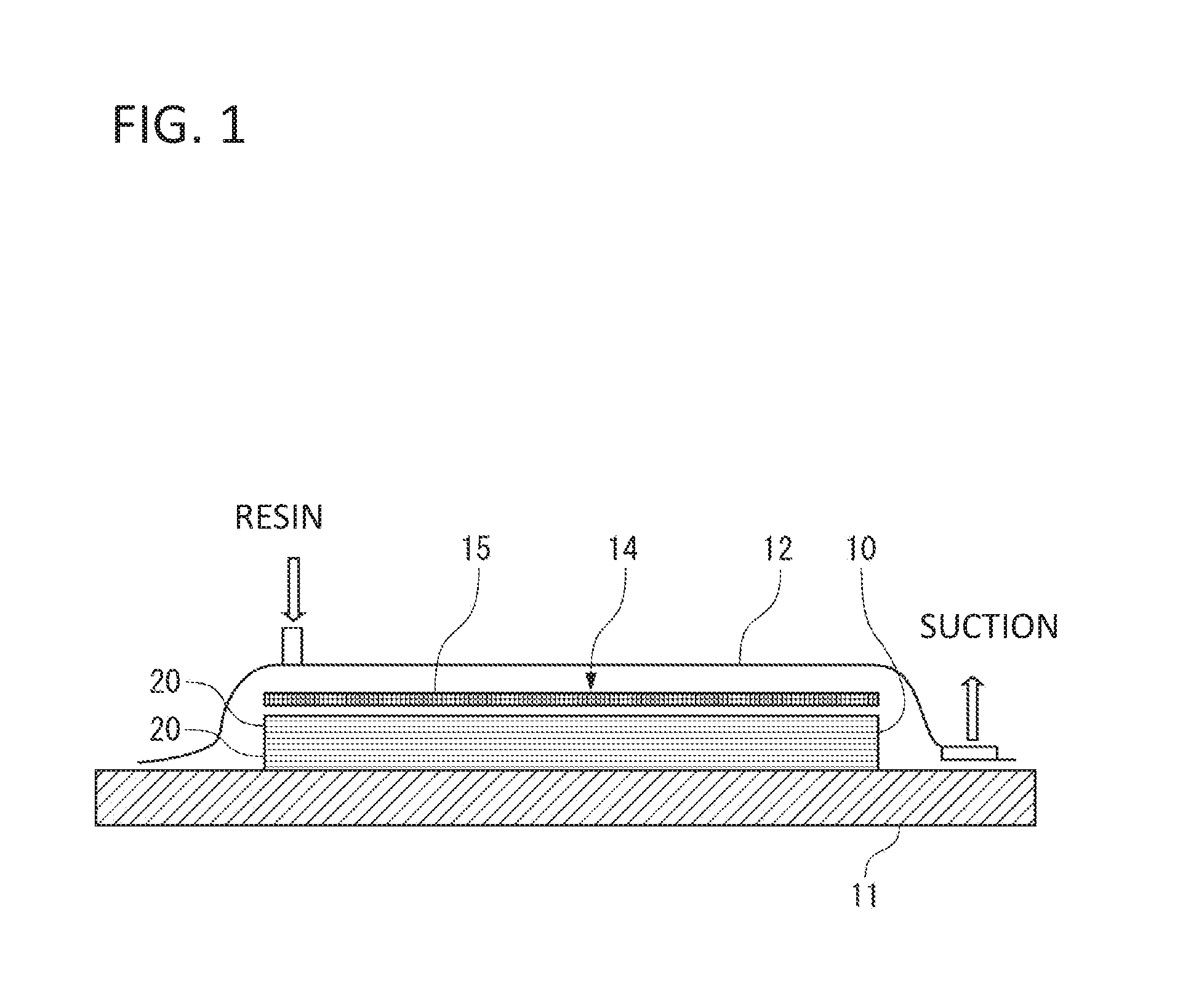
BACKGROUND OF THE INVENTION[0001]1. Field of the Invention[0002]The present invention relates to a method of stacking fiber substrates which are used for fiber-reinforced resin molding by a resin injection method, and to a fiber substrate group composed of stacked fiber substrates.[0003]2. Description of the Related Art[0004]Vacuum assisted resin transfer molding (VaRTM) in which a resin (matrix resin) is injected into a cavity depressurized by evacuation has been practiced as a cost-competitive technique of fiber-reinforced resin molding, and structural members of an aircraft molded by VaRTM have been put into practical use.[0005]When VaRTM is performed, a resin diffusion medium in a mesh form which presents a lower flow resistance to the resin than a fiber substrate is disposed on the surface of the fiber substrate to enhance the impregnation property of the resin (Japanese Patent No. 5322920). The resin injected into the cavity passes through the resin diffusion medium and is dif...

Claims


Application Information

Patent Timeline
IPC IPC(8): B29C70/44B29C70/22B32B5/12B29C65/48
CPCB29C70/443B29C65/486B29C70/22B32B5/12B32B2603/00B29K2105/101B29L2009/00B32B2260/023B32B2260/046B29K2101/12B29C43/12B29C70/202B32B37/0076B32B2037/1215B32B2250/20Y02T50/40
Inventor AKIYAMA, HIROMICHIHORIZONO, HIDEKIKISHIMOTO, KAZUAKISHINYA, MASAHIROSUZUKAKE, SHINYA
Owner MITSUBISHI AIRCRAFT
Learn More