Vehicle door power lock actuator

Active Publication Date: 2016-08-25
TRI MARK CORP
View PDF1 Cites 6 Cited by
  • Summary
  • Abstract
  • Description
  • Claims
  • Application Information

AI Technical Summary

Benefits of technology

The power door lock actuator has a motor and a linear drive that can lock or unlock the door lock mechanism. A centrifugal clutch is used to minimize the loads on the linear drive during startup and stopping. Additionally, the actuator has a unique screw and carriage design that reduces friction and wear, and increases efficiency and lifespan.

Problems solved by technology

If the screw / carriage or rack and pinion is directly linked to the locking mechanism, manual operation with a key may be hindered or rendered difficult since the motor has to be back driven.
Conventional slip clutch driven actuators for a vehicle door lock typically have a limited life due to the hard start and stop of the clutch engagement, which creates excessive wear on the screw / carriage or rack and pinion assembly.

Method used


Image

  • Vehicle door power lock actuator
  • Vehicle door power lock actuator
  • Vehicle door power lock actuator

Examples


Embodiment Construction

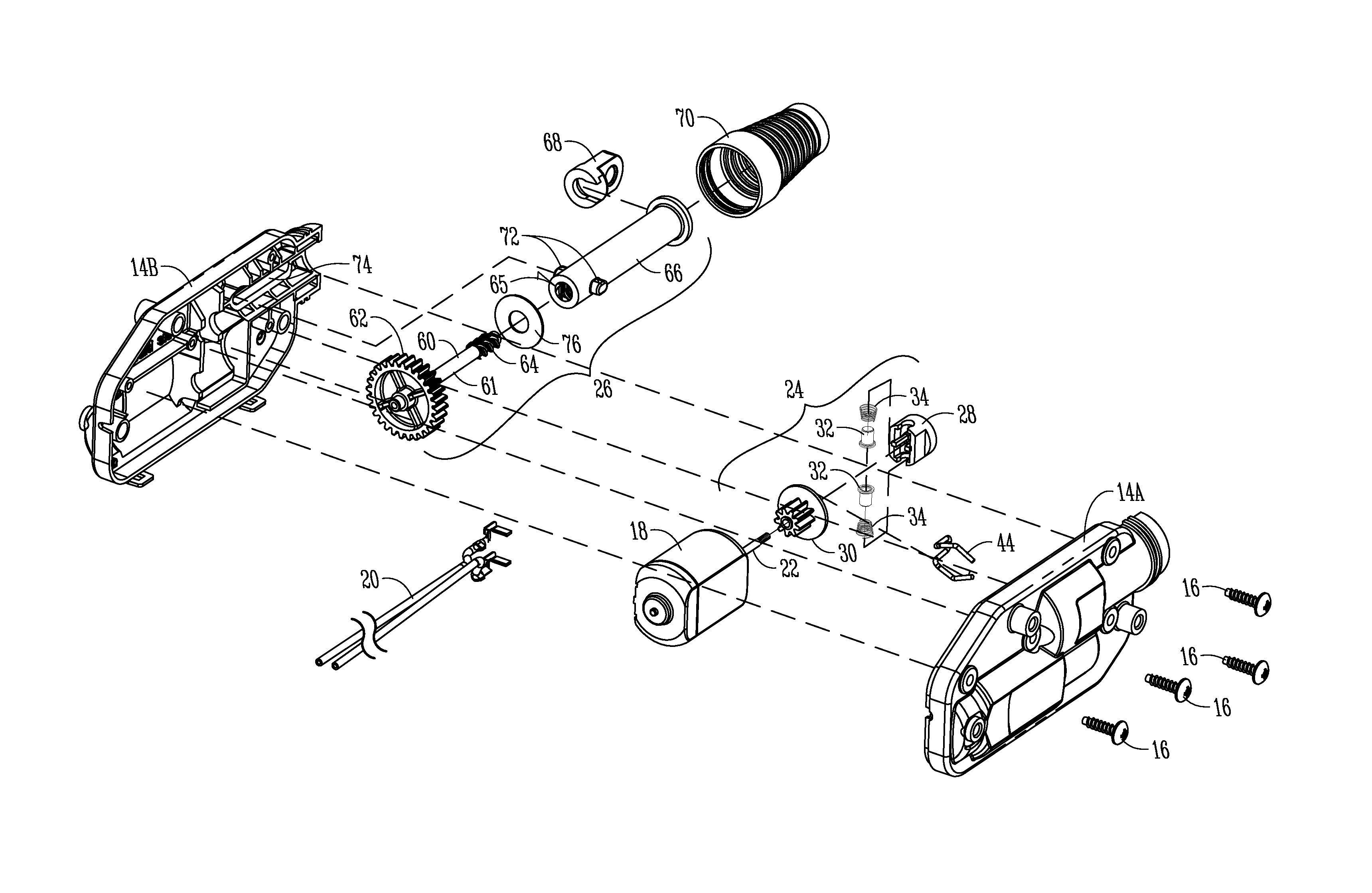
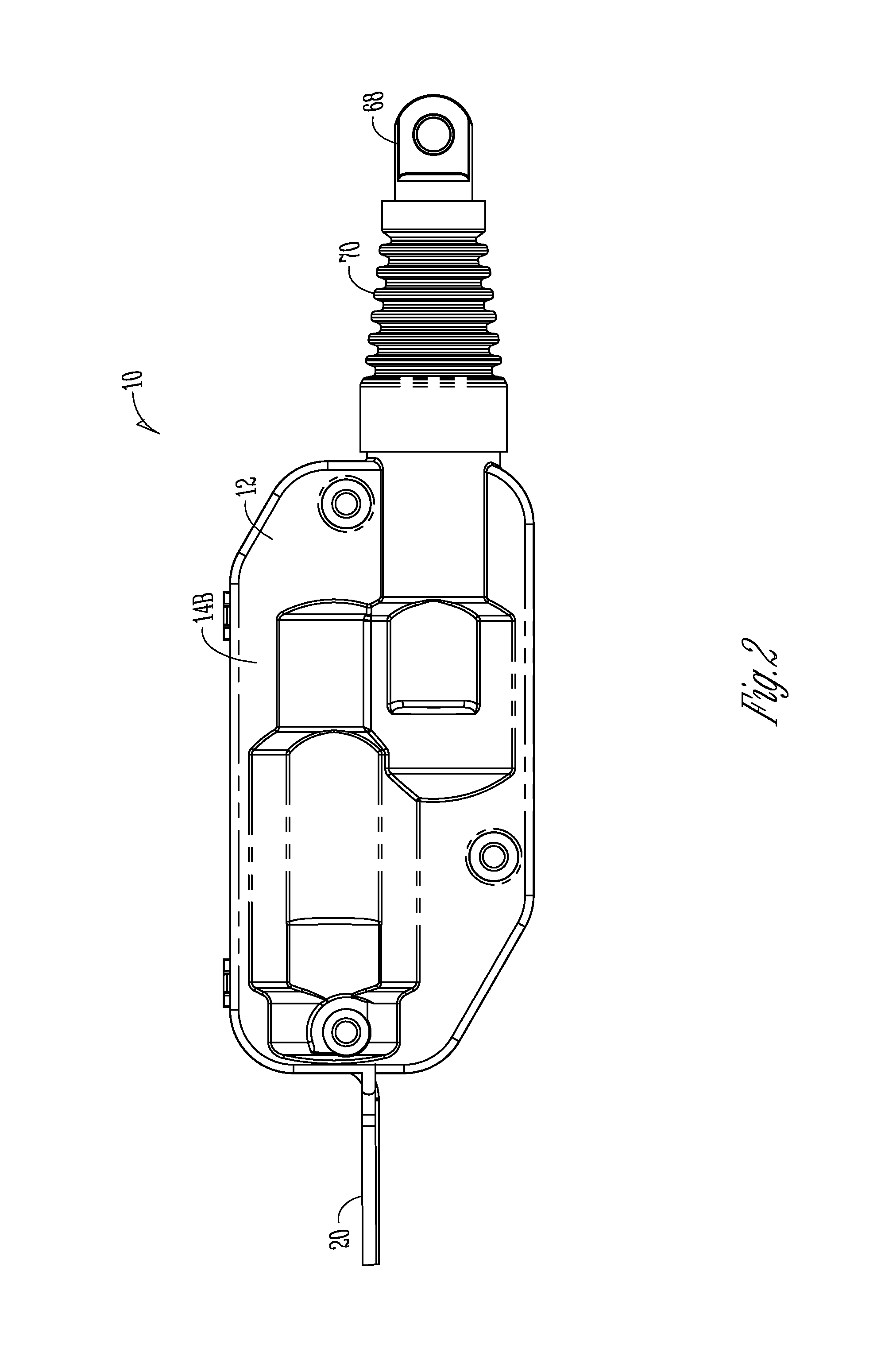
[0041]The power lock actuator of the present invention is generally designated by the reference numeral 10 in the drawings. The actuator 10 includes a housing or cover 12, preferably formed in two halves 14A, 14B secured together by snaps and / or fasteners, such as screws 16. A reversible electric motor 18 is mounted in the cover 12 and has a wiring harness 20 operatively connected to the vehicle battery or other electrical power source for energizing the motor 18.

[0042]The motor 18 includes a rotatable output shaft 22. A centrifugal clutch assembly 24 is mounted on the shaft 22. A linear drive assembly 26 is coupled to the clutch assembly 24 and to the power lock mechanism (not shown) of the vehicle door. When the motor 18 is energized, the clutch assembly 24 will actuate the linear drive 26 which provides an extension or retraction so as to lock and unlock the door lock mechanism.

[0043]The centrifugal clutch assembly 24 includes a hub 28 press fit on the motor shaft 22 and a pinion...


PUM


Abstract

A power lock actuator is provided for a door lock mechanism of a vehicle. The actuator includes an electric motor, a linear drive, and a slip clutch between the motor and the linear drive. The clutch includes a dual-lobe pinion for pulsed energy transmission from the motor to the linear drive, to provide soft starts and stops, which extend the life of the drive assembly 26. The linear drive includes a screw with multiple, discontinuous male thread segments to minimize friction with female threads on the extendible and retractable carriage, thereby minimizing wear between the screw and the carriage.

Description

FIELD OF THE INVENTION[0001]The invention is directed to a linear actuator for a power lock of a vehicle door.BACKGROUND OF THE INVENTION[0002]Vehicle doors usually have a lock mechanism, which often times is locked and unlocked by an electrically powered actuator. One common design for such power lock actuators is a linear push / pull action for electrically locking and unlocking the door locking mechanism. A typical power lock actuator includes an electrical motor, and a rotary-to-linear transmission mechanism which translates rotary motion from the motor output shaft to a linear motion for locking and unlocking the door lock mechanism. The rotary-to-linear mechanism includes a reversibly rotatable screw and carriage, or a rack and pinion, wherein the motor drives a pinion gear which linearly moves the rack or carriage, which in turn is mechanically coupled to the lock mechanism of the door.[0003]It is customary for motor vehicle doors to be provided with locks having a manual relea...

Claims


Application Information

Patent Timeline
IPC IPC(8): E05B81/06F16D43/18E05B81/34E05B81/46
CPCE05B81/06E05B81/34F16D43/18E05B81/46E05B81/25E05B2047/0027F16D5/00
Inventor KRAUS, JASON J.WICKSTROM, ERIC
Owner TRI MARK CORP
Why Eureka
Try Eureka