Pump

a technology of connecting lines and pumps, applied in the field of pumps, can solve the problems of considerable complexity in the sealing of the fuel pump, and achieve the effects of less expensive manufacture, simplified mounting, and reduced manufacturing costs

Inactive Publication Date: 2016-08-25
CONTINENTAL AUTOMOTIVE GMBH
View PDF1 Cites 3 Cited by
  • Summary
  • Abstract
  • Description
  • Claims
  • Application Information

AI Technical Summary

Benefits of technology

[0015]According to one aspect of the invention the bore can be configured for receiving a plug. As a result, the connector lines can be routed from outside as far as the pump and can be contacted via a plug-in connection with the connector lines that run in the interior of the pump. The split embodiment of the connector lines has the advantage that the electric motor can already be contacted in advance during the assembly of the pump, whereas the contact with the energy supply is performed at a later time, for examp

Problems solved by technology

It is disadvantageous that, in order to prevent permeation and leaks, the seal of

Method used


Image

  • Pump
  • Pump

Examples


Embodiment Construction

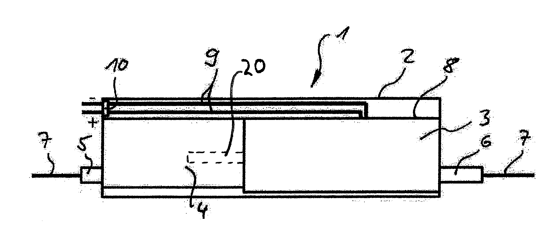
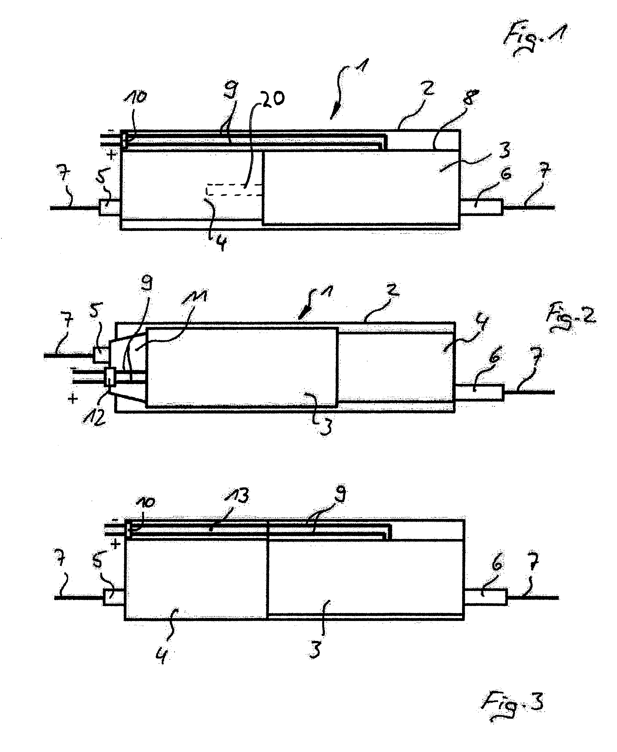
[0020]FIG. 1 shows a fuel pump 1 for delivering fuel from a fuel container to the internal combustion engine of a motor vehicle, the fuel pump 1 being arranged outside the fuel container. The fuel pump 1 consists of a housing 2, in which an electric motor 3 and at least one pumping stage 4, which can be driven by a shaft 20 of the electric motor 3 are arranged. An inlet 5 and an outlet 6 are arranged on opposite sides of the fuel pump 1. The inlet 5 is connected via a forward feed line 7 to the fuel container (not shown), with the result that the pumping stage 4 can draw in fuel via said forward feed line 7. From the pumping stage 4, the fuel is subsequently delivered by the electric motor 3 to the outlet 6 and from there via the forward feed line 7 to the internal combustion engine (likewise not shown). The housing 8 of the electric motor 3 is connected in a sealed manner to the pump outlet of the pumping stage 4 and the outlet 6, with the result that fuel delivered from the pumpin...


PUM


Abstract

A pump has a housing, in which an electric motor and at least one pump stage that can be driven by a shaft of the electric motor are arranged. An inlet and an outlet are located on opposite sides of the pump housing. Connection lines for contacting the electric motor 3 are led through the inlet side of the pump housing to the electric motor.

Description

CROSS REFERENCE TO RELATED APPLICATIONS[0001]This is a U.S. national stage of application No. PCT / EP2014 / 071603 filed on Oct. 9, 2014. Priority is claimed on German Application No. DE10 2013 220 451.5 filed Oct. 10, 2013, the content of which is incorporated here by reference.BACKGROUND OF THE INVENTION[0002]1. Field of the Invention[0003]The subject matter of the invention is a pump having a housing, in which an electric motor and at least one pumping stage driven by a shaft of the electric motor are arranged, an inlet and an outlet which are arranged on opposite sides of the pump, and connector lines for contacting the electric motor.[0004]2. Description of the Prior Art[0005]Pumps of this type are known and are used to deliver liquids and gases, in particular fuel in a motor vehicle. The pumps can be arranged both inside and outside the fuel container. Regardless of the arrangement, the fuel is drawn in via an inlet, brought to the desired pressure level in the pumping stage, and...

Claims


Application Information

Patent Timeline
IPC IPC(8): F02M37/08
CPCF04B17/03F04B35/04F04B39/121F04B53/16F02M2037/082F04D29/426F04C2240/803F04D13/0693F02M37/08F04C11/008
Inventor VOLKER, MARC
Owner CONTINENTAL AUTOMOTIVE GMBH
Why Eureka
Try Eureka