Combined seal ring with encoder and rolling bearing unit with encoder

Active Publication Date: 2016-08-25
NSK LTD
View PDF12 Cites 2 Cited by
  • Summary
  • Abstract
  • Description
  • Claims
  • Application Information

AI Technical Summary

Benefits of technology

The present invention improves the sealability of the fitting part of a rotating cylindrical portion of a slinger and the outer circumferential surface of an inner race member. This is achieved by setting the inner circumferential surface of the rotating cylindrical portion to a stepped cylindrical surface, and fitting the small-diameter portion of the rotating cylindrical portion to the inner race member by tight fit. This prevents the enlargement of the small-diameter portion from being transmitted to the rotating circular ring portion, and ensures a small inner diameter of the encoder. The use of a material obtained by solidifying the permanent magnet material as the encoder further increases the interference, and a lip is not formed on the inner circumferential surface of the encoder, allowing for a larger tightening force.

Problems solved by technology

In a first example having the above-mentioned structure in the related art, the combined seal ring with an encoder 10 can effectively prevent entrance of relatively large substance such as dust, but has difficulty in reliably preventing intrusion of rainwater, muddy slurry, or the like.
The intrusion of moisture into the annular space 8 causes degradation in durability of the bearing unit due to degradation of a lubricant, which is not desirable.
Similarly, it is difficult to satisfactorily secure sealability of the fitting part using only the combined seal ring with an encoder 10 having the above-mentioned structure in the related art.
However, in the second example having the above-mentioned structure, it is difficult to satisfactorily secure sealability of the fitting part of the rotating cylindrical portion 22a of the slinger 15a and the outer circumferential surface of the hub 3a for the following reasons.
Since it is difficult to greatly deform the portion which will be the lip portion 24 in this way, it is difficult to secure the interference of the lip portion 24 to be great.
Accordingly, without securing the great interference to increase the bending deformation, it is not possible to secure a satisfactory tightening force.
However, since the material of the lip portion 24 is not likely to be elastically deformed, it is difficult to secure a satisfactory tightening force in spite of securing of the interference.
As a result, even in the second example having the above-mentioned structure, it is difficult to satisfactorily secure sealability of the fitting part of the rotating cylindrical portion 22a of the slinger 15a and the outer circumferential surface of the hub 3a.

Method used


Image

  • Combined seal ring with encoder and rolling bearing unit with encoder
  • Combined seal ring with encoder and rolling bearing unit with encoder
  • Combined seal ring with encoder and rolling bearing unit with encoder

Examples


first example of embodiment

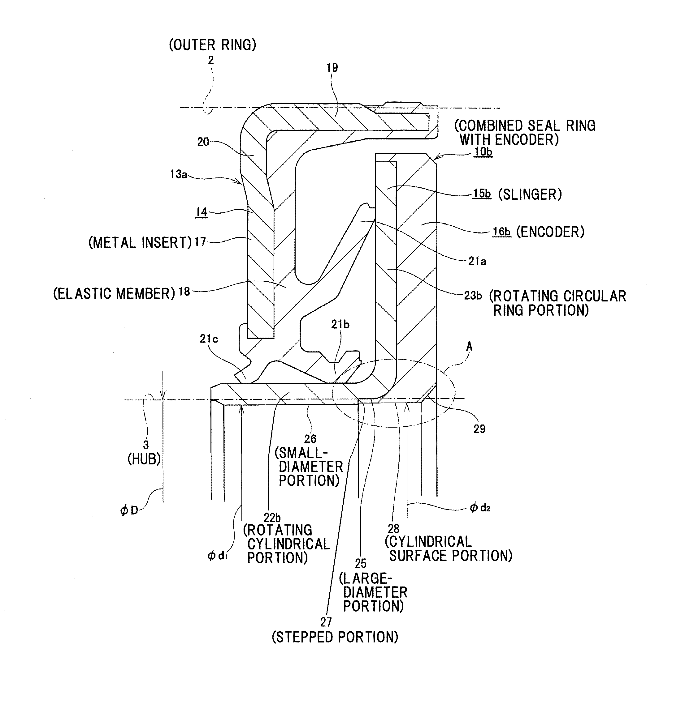
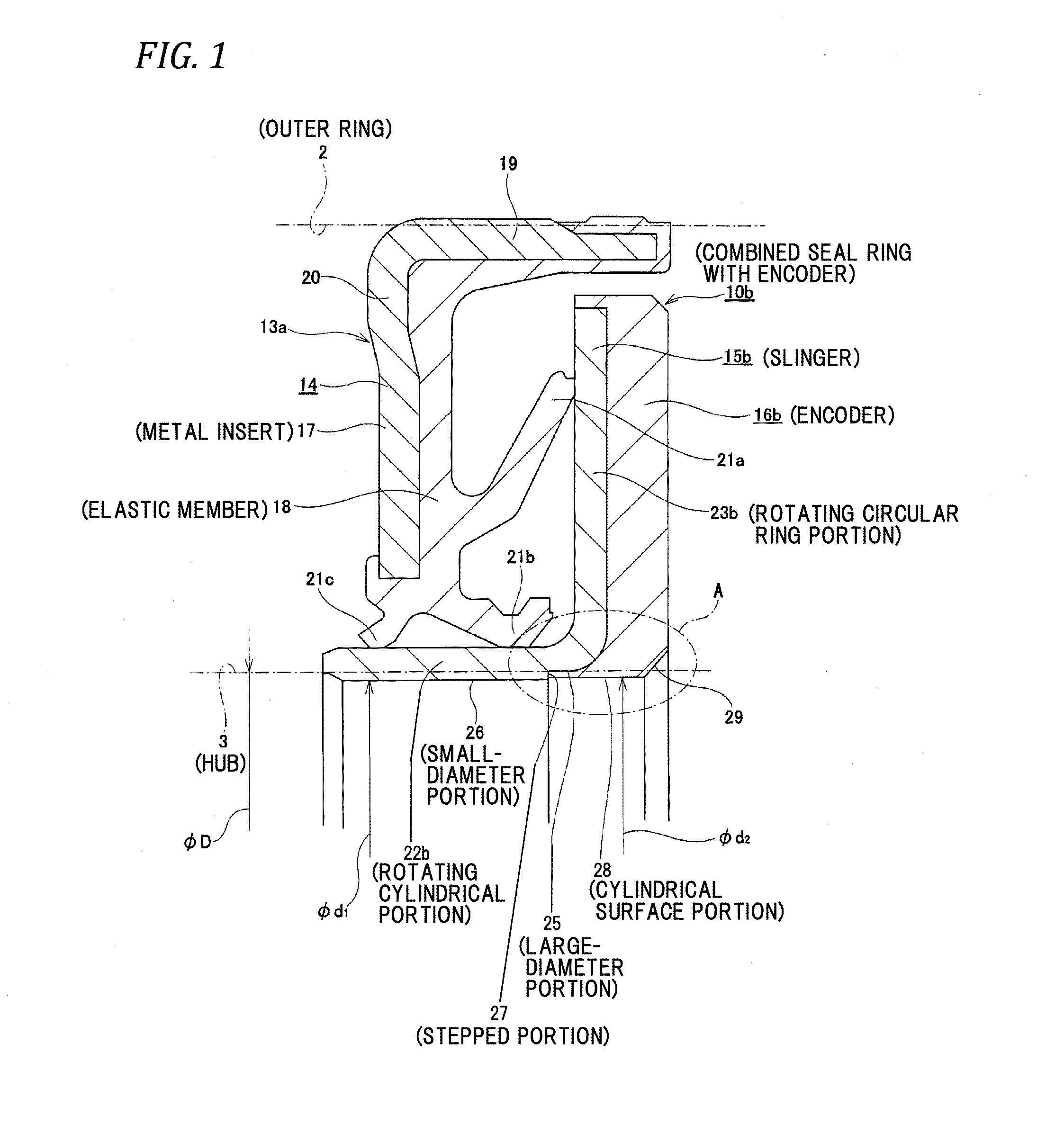
[0042]A first example of an embodiment of the present invention will be described below with reference to FIGS. 1 to 4. This example is characterized by a partial structure that can improve sealability of a fitting part of a rotating cylindrical portion 22b of a slinger 15b and an outer circumferential surface of a hub 3 using an inner circumferential portion of an encoder 16b. Since the other configurations and operational advantages including the entire structure of a rolling bearing unit with an encoder are basically the same as those of the first example having the above-mentioned structure in the related art, like elements are referenced by like reference numerals and illustration and description thereof will not be repeated or will be described in brief. Features of this example will be mainly described below.

[0043]A combined seal ring with an encoder 10b according to this example includes a seal ring 14 and a slinger 15b, which constitute a combine seal ring 13a, and an encod...

second example of embodiment

[0060]A second example of the embodiment of the present invention will be described below with reference to FIGS. 5 and 6. This example provides a structure which is more suitable for a case in which the content of the magnetic material is less (for example, ranges from 50 wt % to 70 wt %) than that in the above-mentioned first example of the embodiment. Specifically, the inner circumferential surface of the encoder 16c includes a partial conical surface portion 35 which is inclined in a direction in which the inner diameter decreases toward the axially inboard and which is formed in an axially outboard end portion, a cylindrical surface portion 28a which is formed in an axially intermediate portion, and a chamfered portion 29 which is formed in an axially inboard end portion. The axially inboard half portion of the cylindrical surface portion 28a having the smallest inner diameter (φd2) is located inside the axially inboard surface of the rotary circular ring portion 23b of the sli...

third example of embodiment

[0063]A third example of the embodiment of the present invention will be described below with reference to FIGS. 7 and 8. This example provides a structure which is suitable for a case in which the content of the magnetic material in the permanent magnet material forming an encoder 16d is less (for example, ranges from 50 wt % to 70 wt %), similarly to the second example of the embodiment. The inner circumferential surface of the encoder 16d includes a partial conical surface portion 35a which is inclined in a direction in which the inner diameter decreases toward the axially inboard and which is formed in an axially outboard end portion, a cylindrical surface portion 28b which is formed in an axial intermediate portion, and a chamfered portion 29 which is formed in an axially inboard end portion. Particularly, in this example, by setting the axial size of the partial conical surface portion 35a to be larger (less in inclination angle) than that in the second example of the embodime...


PUM


Abstract

A slinger has a substantially L-shaped cross-section and includes a rotating cylindrical portion and a rotating circular ring portion. An inner circumferential surface of the rotating cylindrical portion is a stepped cylindrical surface in which a large-diameter portion formed at a portion close to the rotating circular ring portion and a small-diameter portion formed in the remainder are continuously connected by a stepped portion. The encoder supported by the rotating circular ring portion is formed by solidifying and securing a molten permanent magnet material in a state that a molding die collides with the stepped portion. An outer diameter of a hub is defined as φD, an inner diameter of the small-diameter portion in a free state is defined as φd1, and an inner diameter of the encoder in a free state is defined as φd2, a relationship of φd1≦φd2<φD is satisfied.

Description

TECHNICAL FIELD[0001]The present invention relates to improvement in a combined seal ring with an encoder that seals off open ends of a rolling bearing which is assembled into a rotation support of various mechanical devices and that detects a rotation speed of a rotary member supported by the rolling bearing and a rolling bearing unit with an encoder including the combined seal ring with an encoder. More particularly, the present invention relates to realization of a structure capable of securing sealability of a fitting part of a rotary cylindrical portion of a slinger and an outer circumferential surface of an inner race member. An example of the rotary support of various mechanical devices is a rolling bearing unit for support of vehicle wheels for supporting vehicle wheels of a vehicle (automobile) with a suspension device.BACKGROUND ART[0002]In order to rotatably support vehicle wheels of an automobile with a suspension device, a rolling bearing unit with an encoder 1 illustra...

Claims


Application Information

Patent Timeline
IPC IPC(8): F16J15/34F16C33/78F16C41/00F16C19/08
CPCF16C33/783F16C33/7883F16C41/007F16C19/186F16J15/3492F16C19/08F16C33/7823F16J15/3456F16C2326/02F16C33/768
Inventor KATO, MEIJI
Owner NSK LTD
Why Eureka
Try Eureka