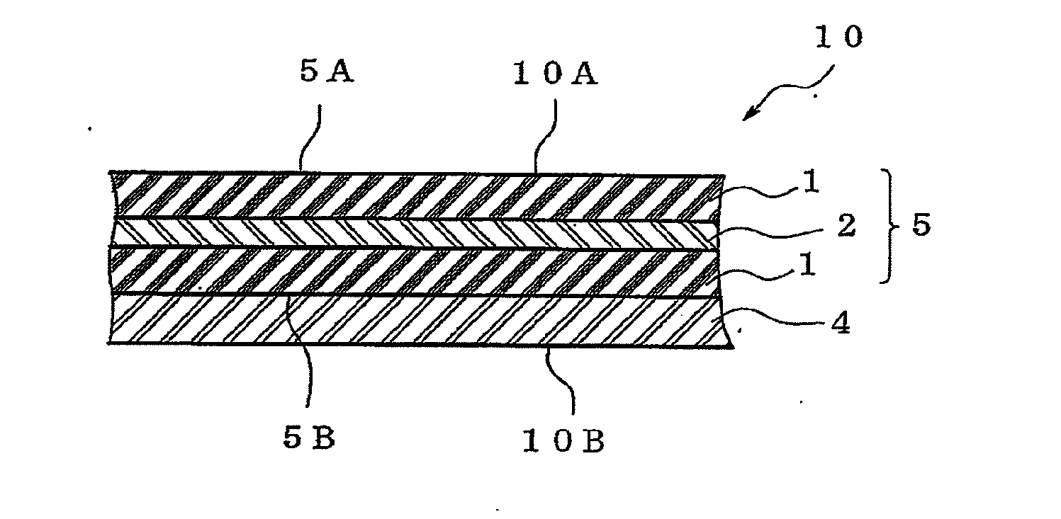
Gasket
a gasket and flame retardant technology, applied in the field of flame retardant gaskets, can solve the problems of adversely affecting human body and environment, large amount of toxic halogen gas, corroding instruments, etc., and achieve the effects of satisfying high flame retardancy, superior effect, and superior sealability against liquid
- Summary
- Abstract
- Description
- Claims
- Application Information
AI Technical Summary
Benefits of technology
Problems solved by technology
Method used
Image
Examples
example 1
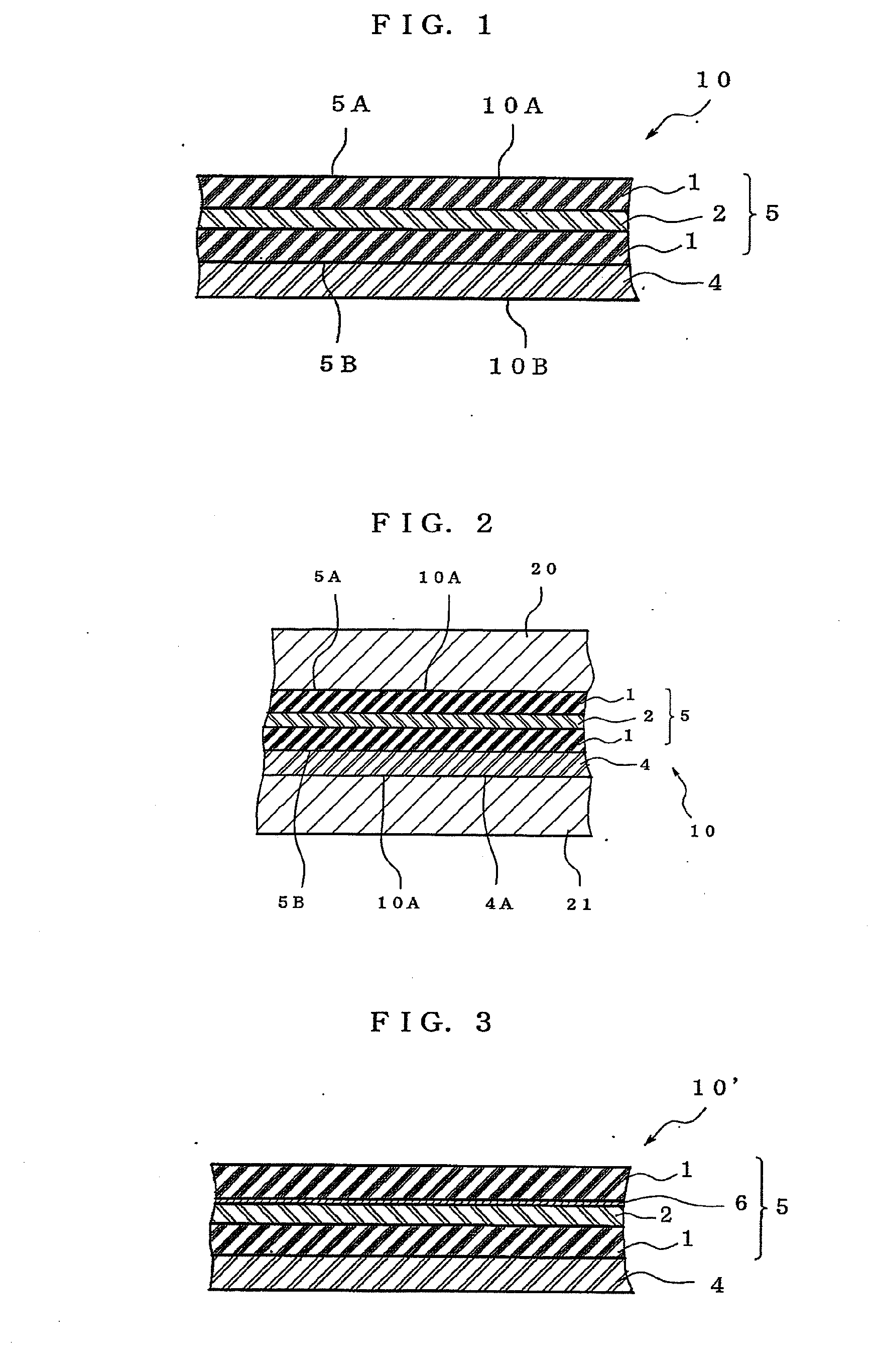
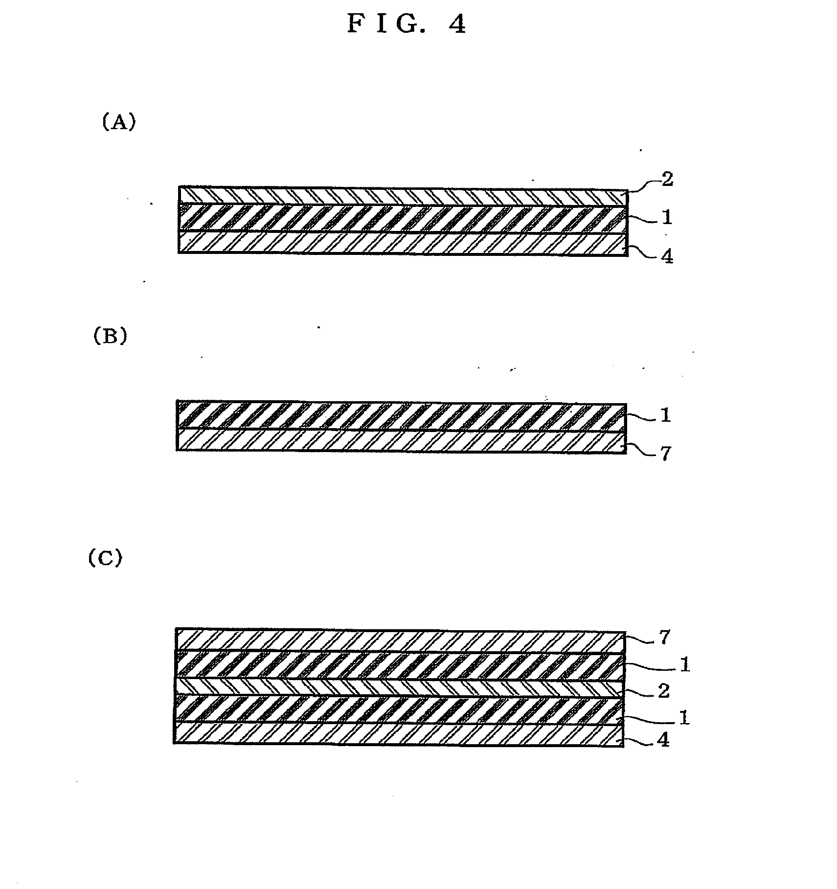
[0159]A thermosetting cold liquid resin (manufactured by Kaneka Corporation, trade name “ACX022”) (100 parts by weight) made from terminal allylation polyoxypropylene wherein an allyl group is bonded to the both terminals of polypropylene glycol having an average molecular weight of about 28000 is mixed with rosin pentaerythritol (10 parts by weight), which is a tackifier resin, heated to 100° C. and stirred for 30 min. After confirmation of transparency of the mixture, dissolution of the tackifier resin in the thermosetting cold liquid resin was confirmed. Thereto were added a curing catalyst (0.05 part by weight), which is made of a solution of platinum / 1,3-divinyltetramethyldisiloxane complex in 2-propanol (complex concentration 3%, manufactured by N.E. CHEMCAT CORPORATION, product name “3% Pt-VTS-IPA solution”), a curing agent (7.65 parts by weight), which is made of a hydrogensiloxane compound having 5 hydrosilyl groups on average in a molecule (manufactured by Kaneka Corporati...
example 2
[0163]In the same manner as in Example 1 except that a primer layer having a thickness of 3 μm, which was made from polyester polyurethane (manufactured by LORD Far East, Inc. “Chemlok459X”), was formed on the polypropylene film of the first adhesive sheet before adhesion of the second adhesive sheet to the first adhesive sheet, a gasket was prepared.
example 3
[0164]To lauryl methacrylate (100 parts by weight) were added 2,2-dimethoxy-1,2-diphenylethan-1-one (photoinitiator, trade name “IRGACURE 651” manufactured by BASF) (0.05 part by weight) and 1-hydroxy-cyclohexyl-phenyl-ketone (photoinitiator, trade name “IRGACURE 184” manufactured by BASF) (0.05 part by weight), the mixture was supplied into a four-mouthed flask, and partially photopolymerized by exposure to UV under a nitrogen atmosphere to give a monomer syrup (partial polymer) having a polymerization rate of 7%. The monomer syrup contains a prepolymer having a molecular weight (Mw) of 6,000,000. The monomer syrup (100 parts by weight) was uniformly mixed with 1,6-hexanedioldiacrylate (trade name “NKester A-HD”: manufactured by Shin-Nakamura Chemical Co., Ltd.) (0.08 part by weight) and tricresylphosphate (TCP) (70 parts by weight), which is a flame retardant, and defoamed to give a photopolymerizable composition (photocurable composition). After 24 hr from the preparation of the ...
PUM
| Property | Measurement | Unit |
|---|---|---|
| Thickness | aaaaa | aaaaa |
Abstract
Description
Claims
Application Information
 - R&D
- Intellectual Property
- Life Sciences
- Materials
- Tech Scout
- Unparalleled Data Quality
- Higher Quality Content
- 60% Fewer Hallucinations
Browse by: Latest US Patents, China's latest patents, Technical Efficacy Thesaurus, Application Domain, Technology Topic, Popular Technical Reports.
© 2025 PatSnap. All rights reserved.Legal|Privacy policy|Modern Slavery Act Transparency Statement|Sitemap|About US| Contact US: help@patsnap.com


