Heat exchanger and refrigeration cycle apparatus using the same heat exchanger

a heat exchanger and cycle apparatus technology, applied in the field of heat exchangers, can solve the problems of significant global warming effect and high global warming potential of hfc-based refrigerant, and achieve the effect of reducing the amount of refrigerant stagnation reducing the pressure loss in the heat-transfer tube of the heat-transferr as a whol

Active Publication Date: 2016-08-25
MITSUBISHI ELECTRIC CORP
View PDF28 Cites 2 Cited by
  • Summary
  • Abstract
  • Description
  • Claims
  • Application Information

AI Technical Summary

Benefits of technology

[0010]According to a heat exchanger of the present invention, the amount of refrigerant stagnated in the heat-transfer tubes can be reduced and the pressure loss in the heat-transfer tubes of the heat exchanger as a whole can be reduced.

Problems solved by technology

While an HFC-based refrigerant is used for refrigeration cycle apparatuses, there is a problem that a HFC-based refrigerant has high global warming potential.
As a result, leakage of refrigerant from a refrigeration cycle apparatus has a significant effect on global warming.

Method used


Image

  • Heat exchanger and refrigeration cycle apparatus using the same heat exchanger
  • Heat exchanger and refrigeration cycle apparatus using the same heat exchanger
  • Heat exchanger and refrigeration cycle apparatus using the same heat exchanger

Examples


embodiment 1

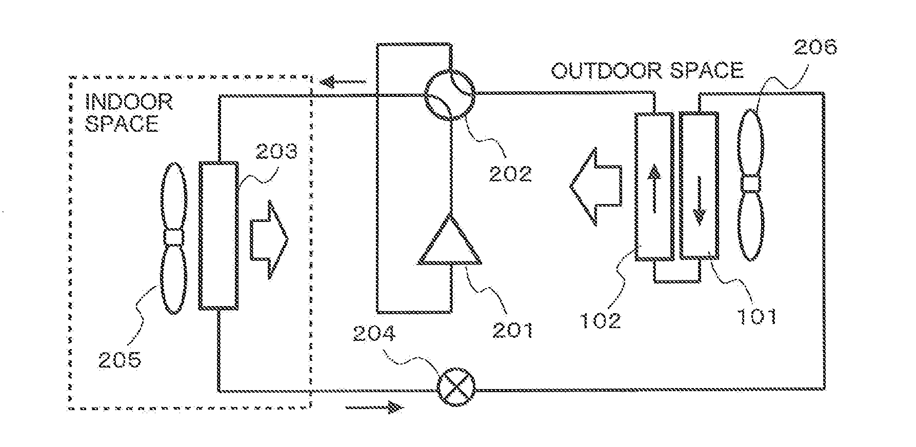
[0023]FIG. 1 is a diagram of a refrigerant circuit that performs a heating operation while a heat exchanger according to Embodiment 1 is mounted on a heat source unit.

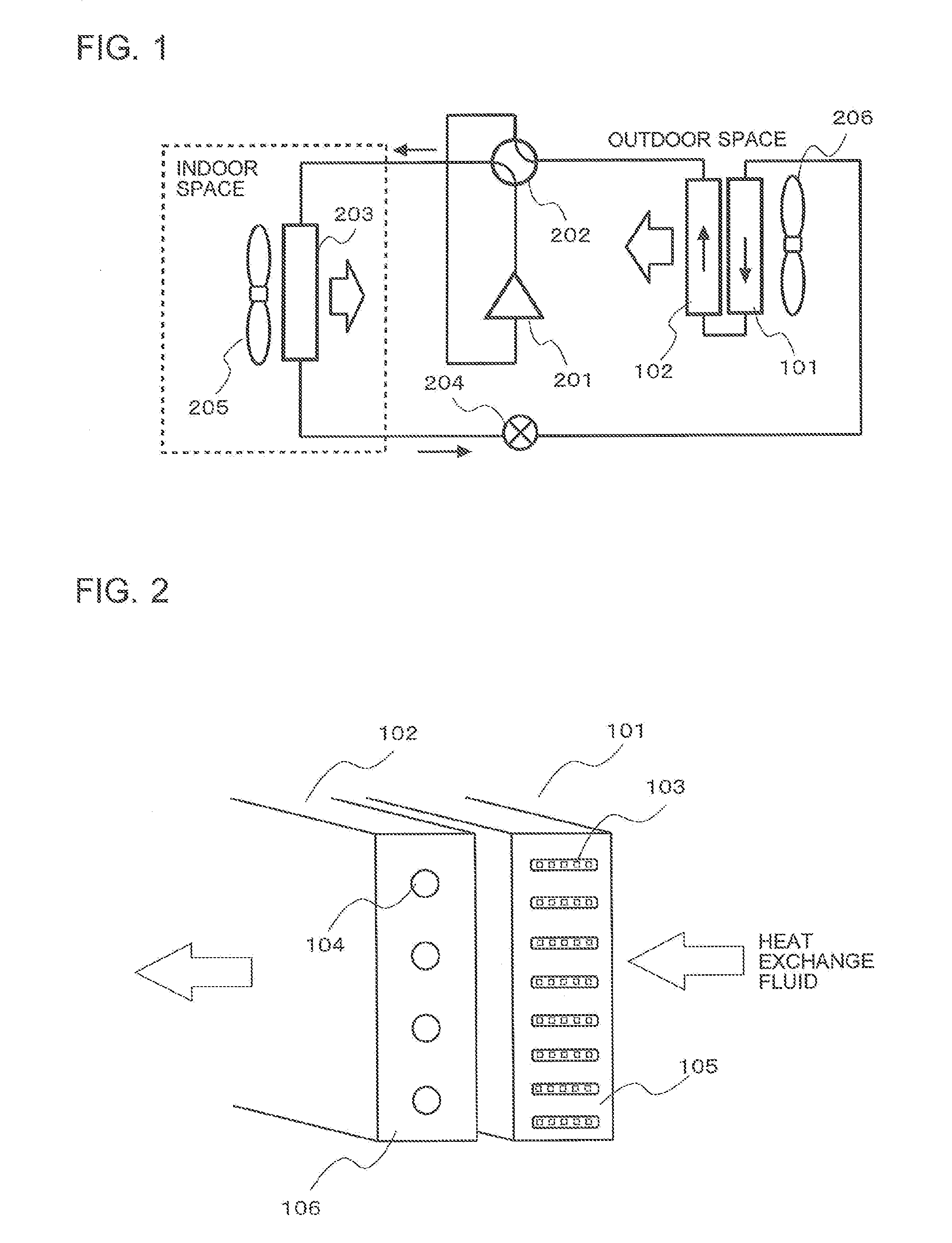
[0024]FIG. 2 is a configuration view of the heat exchanger according to Embodiment 1.

[0025]A refrigeration cycle apparatus includes a compressor 201 that compresses gas refrigerant, a four-way valve 202 that switches a flow path of refrigerant discharged from the compressor 201, a use side heat exchanger 203 that exchanges heat between indoor air and refrigerant, an expansion valve 204 that decompresses refrigerant, and heat source side heat exchangers 101, 102 that exchange heat between outdoor air and refrigerant, which are connected by a refrigerant pipe.

[0026]The use side heat exchanger 203 is disposed adjacent to the use side air-sending device 205. The use side air-sending device 205 sends the indoor air, which is a heat exchange fluid, to the use side heat exchanger 203. The heat source side heat exchangers 101,...

embodiment 2

[0087]Referring to FIG. 8, the heat exchanger according to Embodiment 2 will be described.

[0088]Since the heat exchanger according to Embodiment 2 basically includes the heat-transfer tubes 103, 104 of the first heat source side heat exchanger 101 and the second heat source side heat exchanger 102 according to Embodiment 1, only differences therebetween will be described.

[0089]FIG. 8 is a schematic view which shows the heat exchanger according to Embodiment 2 is applied to an outdoor unit.

[0090]In Embodiment 2, three row of heat exchangers are disposed in the flowing direction of the heat exchange fluid, which are made up of two rows of the first heat source side heat exchanger 101 having an L-shaped and one row of the second heat source side heat exchanger 102 having a plate shape. A width dimension of the second heat source side heat exchanger 102 is smaller than a width dimension of the straight portion of the first heat source side heat exchanger 101. Further, a height dimension...


PUM


Abstract

A heat exchanger including a first heat exchanger disposed on upstream side of a heat exchange fluid and a second heat exchanger disposed on downstream side of the heat exchange fluid, which are connected in series in a flow path of a heat medium, wherein the heat medium flows from the first heat exchanger to the second heat exchanger so as to be parallel to the flow of the heat exchange fluid when the heat exchanger serves as an evaporator, the heat medium flows from the second heat exchanger to the first heat exchanger so as to be opposed to the flow of the heat exchange fluid when the heat exchanger serves as a condenser, and a sum of flow path volume of first heat-transfer tubes of the first heat exchanger is smaller than a sum of flow path volume of second heat-transfer tubes of the second heat exchanger.

Description

TECHNICAL FIELD[0001]The present invention relates to a heat exchanger having a plurality of rows of heat-transfer tubes through which refrigerant flows with respect to a flowing direction of heat exchange fluid (for example, air).BACKGROUND ART[0002]While an HFC-based refrigerant is used for refrigeration cycle apparatuses, there is a problem that a HFC-based refrigerant has high global warming potential. As a result, leakage of refrigerant from a refrigeration cycle apparatus has a significant effect on global warming. Accordingly, a technique of reducing the amount of refrigerant to be sealed in the refrigeration cycle apparatus is required.[0003]During operation of the refrigeration cycle apparatus, since a major part of refrigerant sealed in the refrigeration cycle apparatus is stagnated in the heat exchanger, it is important to reduce the amount of stagnating refrigerant by reducing the volume of the heat-transfer tubes of the heat exchanger.[0004]In some conventional heat exc...

Claims


Application Information

Patent Timeline
Patent Type & Authority Applications(United States)
IPC IPC(8): F28D7/00F28F21/08
CPCF25B13/00F25B39/00F25B2313/0254F28D7/0066F28D1/05316F28D1/05366F28F21/084F28D1/0435F28F2210/08
Inventor HIGASHIIUE, SHINYAISHIBASHI, AKIRAOKAZAKI, TAKASHIITO, DAISUKEMATSUI, SHIGEYOSHIUGAJIN, YUKI
Owner MITSUBISHI ELECTRIC CORP
Why Eureka
Try Eureka