Antenna device

a technology of antenna device and antenna array, which is applied in the direction of waveguide, individually energised antenna array, waveguide type devices, etc., can solve the problems of increasing the area of the outer conductor, complicated distribution line configuration, and increasing the size of the antenna device, so as to improve the transmission loss

Active Publication Date: 2016-08-25
HITACHI METALS LTD
View PDF2 Cites 3 Cited by
  • Summary
  • Abstract
  • Description
  • Claims
  • Application Information

AI Technical Summary

Benefits of technology

[0034]The antenna device of the present invention allows for a further improvement in transmission loss.

Problems solved by technology

In recent years, a mobile phone base station antenna, for example, has been required to be compatible with a plurality of frequency bands, and the configuration of the distribution lines has therefore been complicated.
Further, constructing the complicatedly configured distribution lines of the antenna device by using the triplate line with the central conductor located between the one pair of outer conductors as described above has increased the area of the outer conductors, and has been likely to increase the size of the antenna device.
However, forming the triplate line into a plurality of layers, and connecting between the respective central conductors of the triplate lines by a connecting member has increased the transmission loss of the high frequency signal at a connecting portion between the central conductors including that connecting member.
However, that antenna device has had the following problem.

Method used


Image

  • Antenna device
  • Antenna device
  • Antenna device

Examples


embodiment

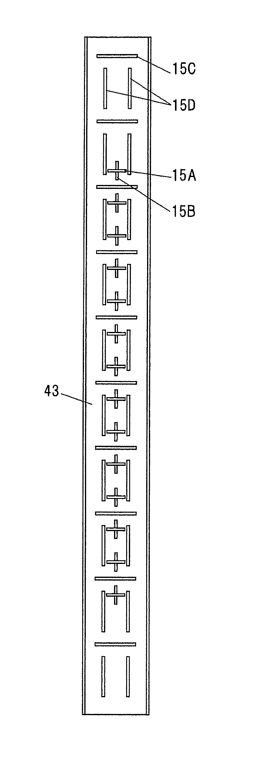
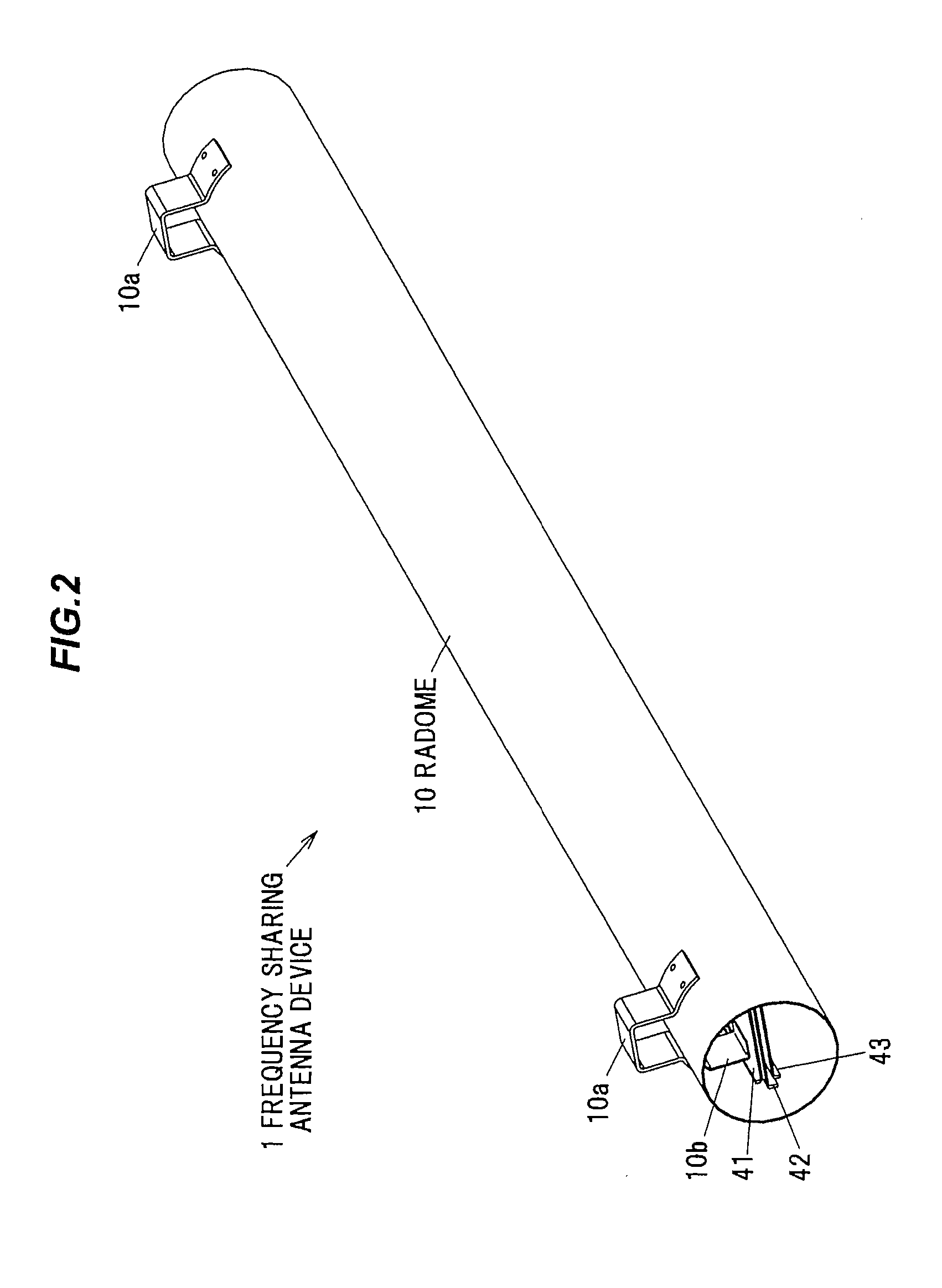
[0064]Below will be described a frequency sharing antenna device as one embodiment of an antenna device according to the present invention, with reference to the drawings. This frequency sharing antenna device is used as a base station antenna for a mobile phone. Note that, although in the following description, the frequency sharing antenna device will be described for use in transmitting a high frequency signal, this frequency sharing antenna device may be used for receiving thereof as well.

[0065](Function Configuration of the Frequency Sharing Antenna Device)

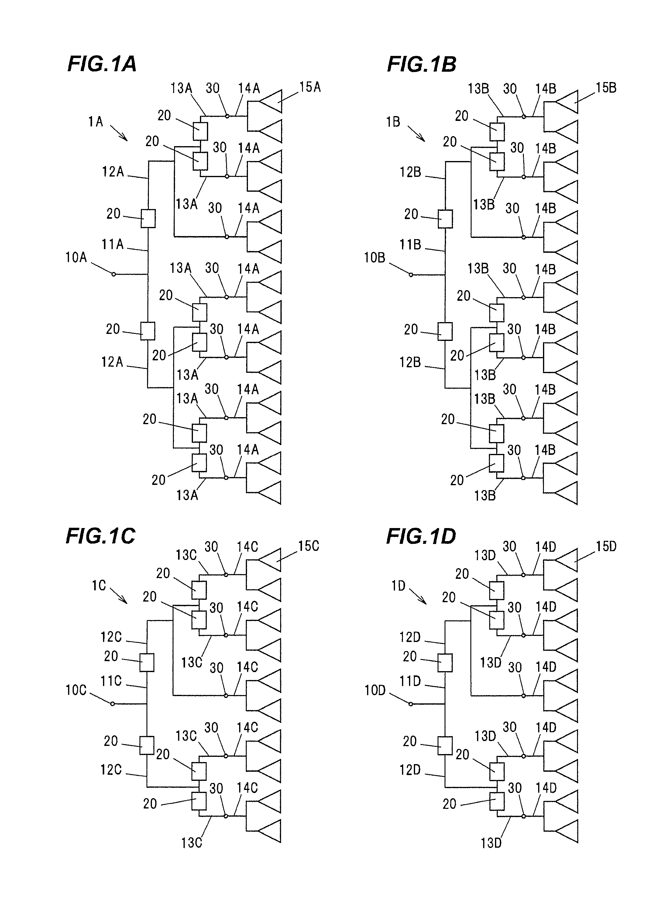
[0066]FIGS. 1A to 1D are schematic diagrams showing function configurations, respectively, of the frequency sharing antenna device in this embodiment. The frequency sharing antenna device is capable of transmitting horizontally polarized and vertically polarized high frequency signals in a band of 1.5 to 2 GHz, and horizontally polarized and vertically polarized high frequency signals in a band of 700 to 800 MHz. Herein, the ...


PUM


Abstract

An antenna device includes a transmission line for propagating high frequency signal, and a plurality of antenna elements connected to the transmission line. The transmission line includes a first plate-shaped conductor, a second plate-shaped conductor, and a third plate-shaped conductor electrically grounded, a first central conductor disposed between the first and second plate-shaped conductors, a second central conductor disposed between the second and third plate-shaped conductors, an electrically connecting member inserted in an inserting hole formed through the second plate-shaped conductor, to electrically connect the first and second central conductors together, and an electrically grounded conductor disposed adjacent to the electrically connecting member. At least one of the first and second central conductors is provided with a through hole formed adjacent to the electrically connecting member, thereby electrically connects together wiring patterns provided on both surfaces, respectively, of a dielectric substrate of the at least one of the first and second central conductors.

Description

[0001]The present application is based on Japanese patent application No. 2015-034308 filed on Feb. 24, 2015, the entire contents of which are incorporated herein by reference.BACKGROUND OF THE INVENTION[0002]1. Field of the Invention[0003]This invention relates to an antenna device. 2. Description of the Related Art[0004]Conventionally, an antenna device is known that is equipped with a transmission line having a triplate structure composed of one pair of plate-shaped conductors and a central conductor located between the one pair of plate-shaped conductors, and a plurality of antenna elements each capable of transmitting a high frequency signal distributed by that transmission line. (See JP-A-2014-110557 (FIG. 5))[0005]The antenna device disclosed in JP-A-2014-110557 (FIG. 5) includes a plate-shaped first outer conductor, a plate-shaped second outer conductor, which is spaced a predetermined distance apart from the first outer conductor, a linear central conductor, which is dispos...

Claims


Application Information

Patent Timeline
Patent Type & Authority Applications(United States)
IPC IPC(8): H01Q21/00H01P3/08
CPCH01P3/08H01Q21/0075H01P3/088H01Q1/246H01Q19/10H01Q21/08H05K1/144H05K2201/10409
Inventor ISO, NAOKIKANETA, MASAHISAKITANO, NOBUAKIOGAWA, TOMOYUKIFUJISHIMA, TSUKASA
Owner HITACHI METALS LTD
Why Eureka
Try Eureka