Smart lighting device, and smart lighting control system and method

a lighting control system and smart technology, applied in the field of lighting technologies, can solve the problems of increasing the energy consumption of the device, limiting the application of the light source, and generally not having wireless communication capabilities of the light sour

Active Publication Date: 2016-08-25
SENGLED OPTOELECTRONICS
View PDF5 Cites 35 Cited by
  • Summary
  • Abstract
  • Description
  • Claims
  • Application Information

AI Technical Summary

Benefits of technology

[0051]The present disclosure provides a smart lighting device with a built-in microphone module and a human detection module. The microphone module may have two operation modes including a sleep mode and a monitor mode. When the human detection module detects human appearance in a surrounding area of the smart lighting device, the microphone module may be waked up to be operated at the monitor mode. Therefore, the microphone module may collect audio signals at the monitor mode when needed, and maintain low power consumption at the sleep mode when not needed. This reduces power consumption of the entire smart lighting device, saves power, and expands the operational duration of the smart lighting device.
[0029]In certain embodiments, a device network may be formed to include multiple smart lighting devices and one or more computing devices such as a server and / or a smart terminal. For example, a human approaching one of the smart lighting devices may be detected by the human detection module of one smart lighting device in the device network to turn on its microphone to collect audio signals of the human. The voice command generated by a cloud server from the collected audio signals may then be used to control other different smart lighting devices in a same network through the cloud server. For example, the software program configured on the cloud server may generate voice commands with respect to each of various different smart lighting devices and to allow centralized control of these smart lighting devices in the same network. In this case, audio signal collected by one smart lighting device may be used to control other smart lighting device(s) via the cloud server.

Problems solved by technology

However, existing smart lighting devices generally do not have wireless communication capabilities and cannot send collected audio signals to a smart terminal via Internet, which limits their applications in various situations.
On the other hand, even though some smart lighting devices may have wireless communication capabilities and voice recognition functions, the microphone may have to be operated in a monitoring mode all the time.
This increases energy consumption of the device.
In addition, oftentimes the collected audio signals are not useful and may occasionally cause false command recognition.
Error messages and false actions may thus occur.

Method used


Image

  • Smart lighting device, and smart lighting control system and method
  • Smart lighting device, and smart lighting control system and method
  • Smart lighting device, and smart lighting control system and method

Examples


Embodiment Construction

[0013]Reference will now be made in detail to exemplary embodiments of the invention, which are illustrated in the accompanying drawings. Hereinafter, embodiments consistent with the disclosure will be described with reference to drawings. Wherever possible, the same reference numbers will be used throughout the drawings to refer to the same or like parts. It is apparent that the described embodiments are some but not all of the embodiments of the present invention. Based on the disclosed embodiment, one of ordinary skill in the art may derive other embodiments consistent with the present disclosure, all of which are within the scope of the present invention.

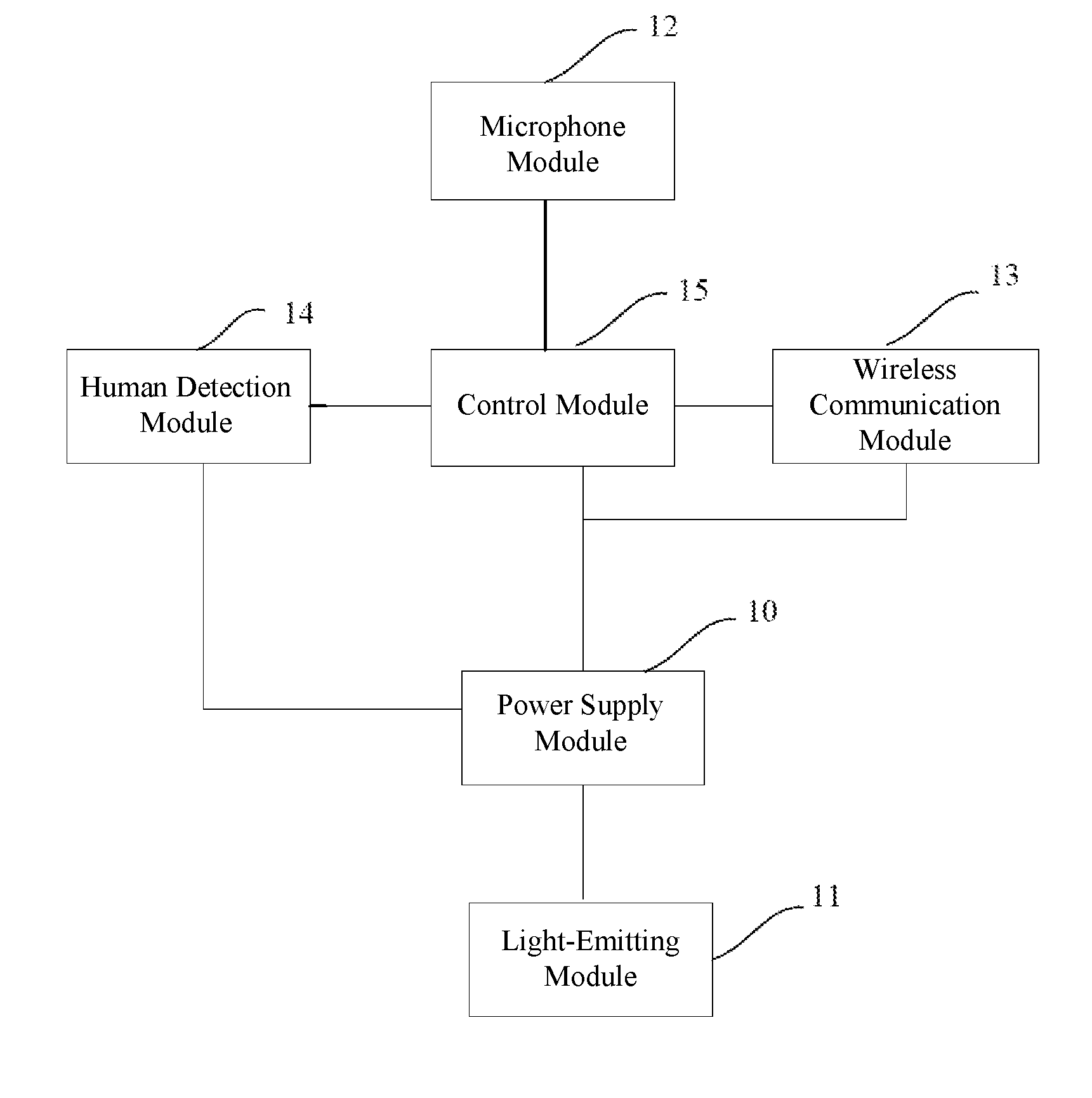
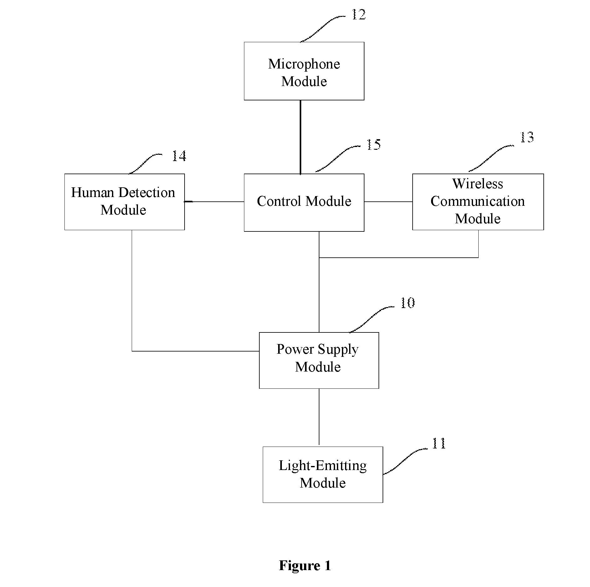
[0014]FIG. 1 is a schematic structure diagram of an exemplary smart lighting device consistent with various disclosed embodiments of the present disclosure. An exemplary smart lighting device may be a smart LED lighting device. As shown in FIG. 1, an exemplary smart lighting device may include a power supply module 10, a light-e...


PUM


Abstract

The present disclosure provides a smart lighting device, and a smart lighting control system and method. The smart lighting device includes a human detection module, a control module, and a microphone module. The microphone module has operation modes including a sleep mode and a monitor mode. The human detection module detects whether a human appears in a surrounding area of the smart lighting device in real-time, and sends a detection signal to the control module when a human appearance is detected. The control module receives and sends the detection signal to the microphone module to switch from a sleep mode to a monitor mode. When receiving a control signal from the control module, the microphone module switches to the monitor mode and collects audio signals in the surrounding area of the smart lighting device. The smart lighting device further includes a wireless communication module for wireless communication.

Description

CROSS-REFERENCES TO RELATED APPLICATIONS[0001]This application is a national stage application under 35 USC §371(c) of PCT Application No. PCT / CN2015 / 077265, entitled “Smart Lighting Device, And Smart Lighting Control System And Method” filed on Apr. 23, 2015, which claims the priority of Chinese Patent Application No. CN201410502762.1, filed on Sep. 26, 2014. The entire disclosure and contents of the above applications are hereby incorporated by reference herein.FIELD OF THE DISCLOSURE[0002]The present disclosure generally relates to the field of lighting technologies and, more particularly, relates to a smart lighting device, a smart lighting control system, and a smart lighting control method.BACKGROUND[0003]Smart lighting devices often include a microphone unit configured to use voices to perform basic controls (such as on / off switching and brightness adjustments) of the lighting devices. However, existing smart lighting devices generally do not have wireless communication capab...

Claims


Application Information

Patent Timeline
Patent Type & Authority Applications(United States)
IPC IPC(8): H05B37/02H05B33/08H05B44/00
CPCH05B37/0227H05B37/0272Y02B20/40H05B37/0236Y02B20/44H05B33/0842Y02B20/48H05B47/19H05B47/125H05B47/115H05B47/105H05B45/00G10L15/22H05B47/12
Inventor SUN, CHAOQUNSHEN, JINXIANG
Owner SENGLED OPTOELECTRONICS
Why Eureka
Try Eureka