Work vehicle and control method for work vehicle

a technology for work vehicles and control methods, applied in the direction of vehicle sub-unit features, propulsion parts, engine-driven generators, etc., can solve the problems of difficult to predict the potential energy or the kinetic energy ahead of time, and the difficulty in using the potential energy and the kinetic energy applied, so as to improve the fuel consumption performance of the work vehicle, increase the target electricity storage amount, and increase the energy recovery amount

Active Publication Date: 2016-09-01
KOMATSU LTD
View PDF5 Cites 7 Cited by
  • Summary
  • Abstract
  • Description
  • Claims
  • Application Information

AI Technical Summary

Benefits of technology

[0023]According to exemplary embodiments of the present invention, the target electricity storage amount is increased when the first travel direction and the second travel direction are different. An operation of the work vehicle in which the first travel direction and the second travel direction become different is called a shuttle action. After decelerating, the speed is then increased in the first travel direction in the shuttle action. Consequently, the electricity received duri...

Problems solved by technology

However, it is difficult to use the potential energy and the kinetic energy applied to the movement of the travel device of the work vehicle in the same way.
A work vehicle is not limited to traveling on a road and th...

Method used


Image

  • Work vehicle and control method for work vehicle
  • Work vehicle and control method for work vehicle
  • Work vehicle and control method for work vehicle

Examples


Embodiment Construction

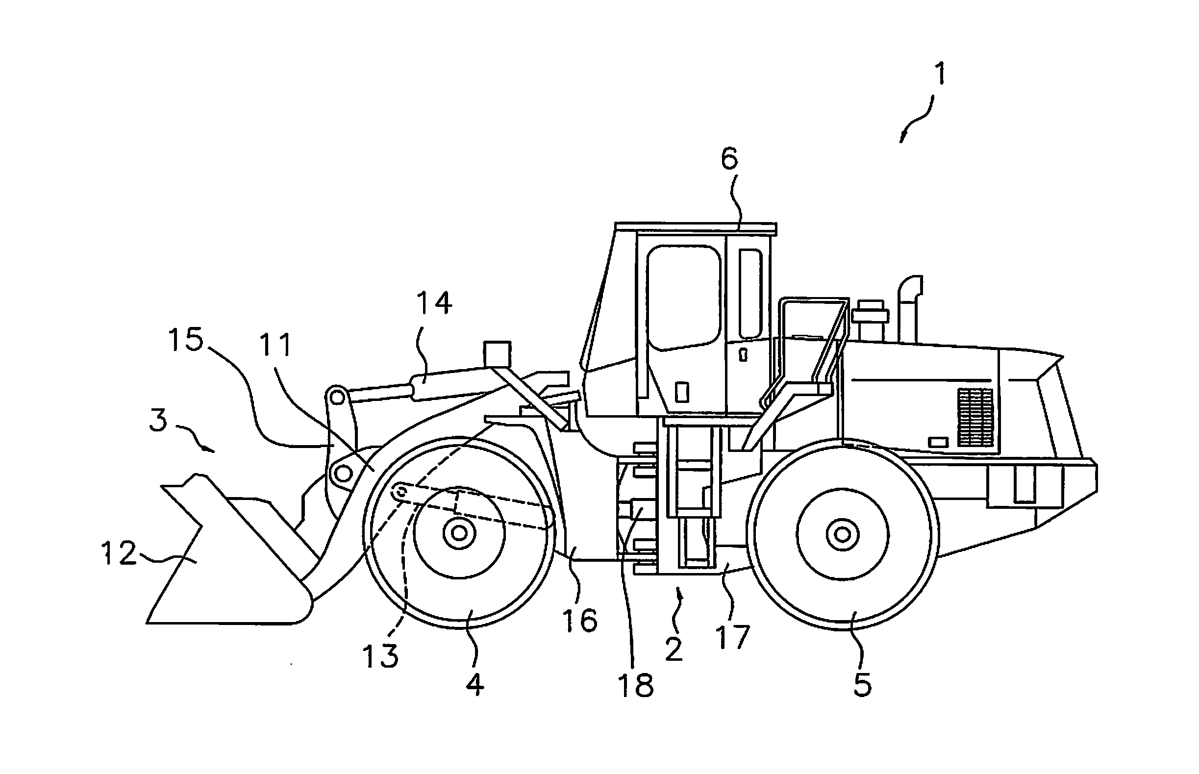
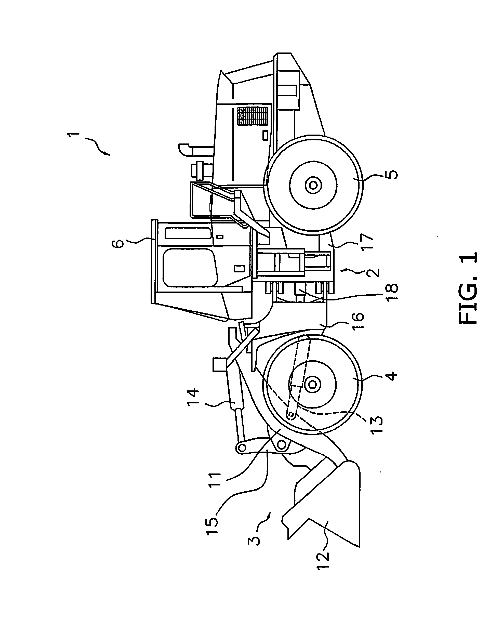
[0035]An exemplary embodiment of the present invention will be explained in detail with reference to the figures. FIG. 1 is a side view of a work vehicle 1 according to an exemplary embodiment of the present invention. As illustrated in FIG. 1, the work vehicle 1 is equipped with a vehicle body frame 2, a work implement 3, traveling wheels 4 and 5, and an operating cabin 6. The work vehicle 1 is a wheel loader and travels due to the traveling wheels 4 and 5 being rotated and driven. The work vehicle 1 is able to carry out work, such as excavation, by using the work implement 3.

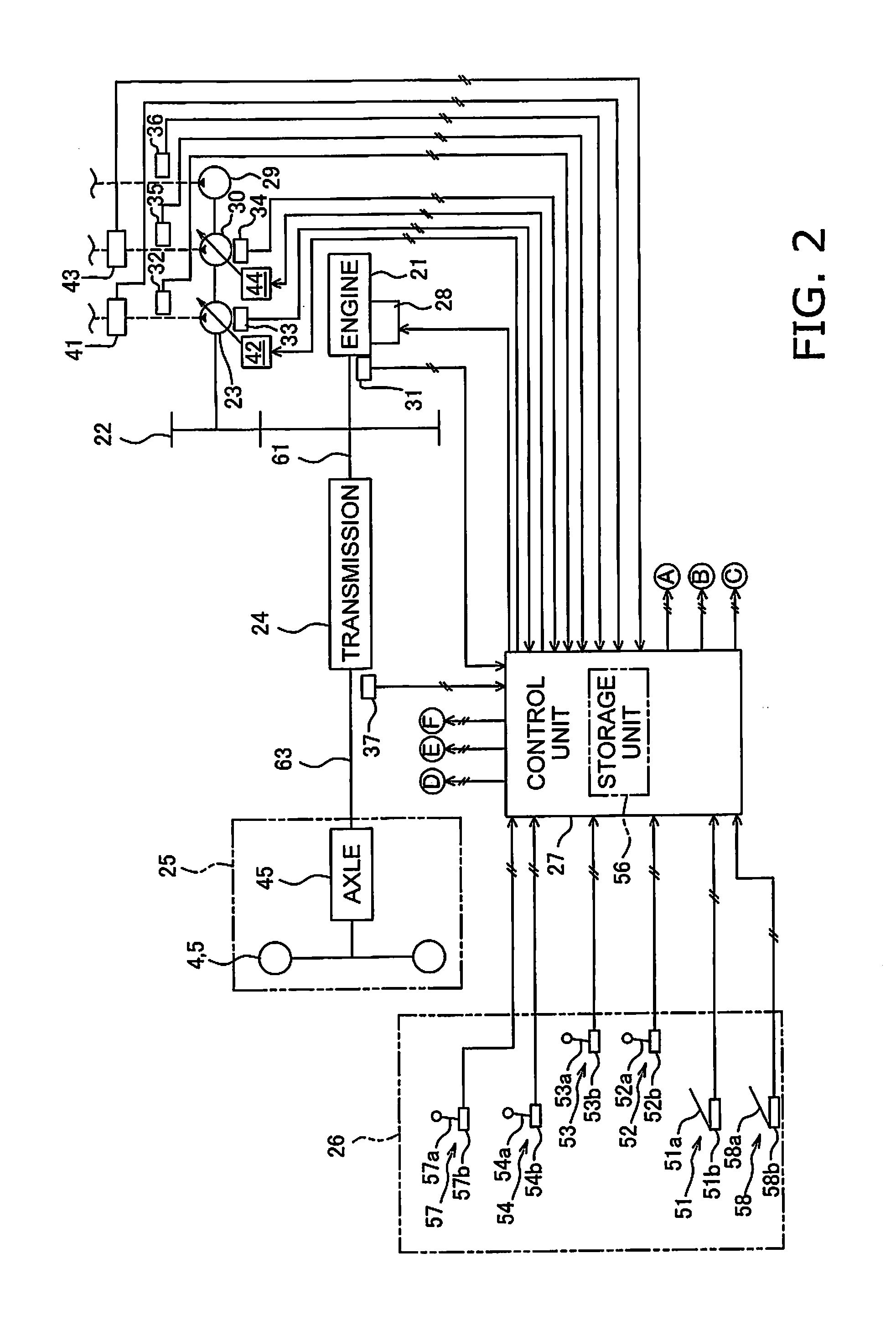
[0036]The vehicle body frame 2 includes a front frame 16 and a rear frame 17. The front frame 16 and the rear frame 17 are attached to each other in a manner that allows tilting in the left-right direction. The work implement 3 and the traveling wheels 4 are attached to the front frame 16. The work implement 3 is driven by hydraulic fluid from a below-mentioned work implement pump 23 (see FIG. 2). The work imp...


PUM


Abstract

A power transmission device of a work vehicle includes a generator, a motor, and an energy storage unit. The energy storage unit stores electricity generated by the generator. A forward/backward travel switch operation device receives an instruction for forward or backward travel from an operator. A vehicle speed detection unit detects the speed of the vehicle. A control unit includes an energy management requirement determination unit. The energy management requirement determination unit determines, on the basis of the difference between a target electricity storage amount and a current electricity storage amount in the energy storage unit, the energy management required power required by the power transmission device for charging the energy storage unit. The energy management requirement determination unit increases the target electricity storage amount when a first travel direction according to the instruction and a second travel direction determined from the vehicle speed are different.

Description

CROSS-REFERENCE TO RELATED APPLICATIONS[0001]This application is a U.S. National stage application of International Application No. PCT / JP2014 / 083431, filed on Dec. 17, 2014. This U.S. National stage application claims priority under 35 U.S.C. §119(a) to Japanese Patent Application No. 2014-016829, filed in Japan on Jan. 31, 2014, the entire contents of which are hereby incorporated herein by reference.BACKGROUND[0002]1. Field of the Invention[0003]The present invention relates to a work vehicle and a control method for the work vehicle.[0004]2. Background Information[0005]Recently, a hybrid-type work vehicle has been proposed that travels using both an engine and a motor. The above-mentioned hybrid-type power transmission device demonstrates the advantage of having an energy recovery function and good fuel consumption in comparison to a conventional power transmission device (referred to below as a “torque converter-type speed variator”) having a torque converter and a multi-stage ...

Claims


Application Information

Patent Timeline
IPC IPC(8): E02F9/20B60W20/00B60L11/18B60L15/20E02F9/22B60K6/28B60L50/16
CPCE02F9/2075B60Y2400/73E02F9/2079E02F9/2253E02F9/202B60K6/28B60L11/1861B60L15/2054B60W20/00E02F3/283E02F9/2285B60K6/365B60K6/48B60W10/10B60W10/08F16H2200/2007F16H3/72B60L2200/40B60L2240/12B60L2240/421B60Y2200/415B60Y2400/11E02F9/2091E02F9/2292E02F9/2296B60L15/2009B60L15/2045B60L2200/36B60L2210/40B60L2240/423B60L2240/441B60L2240/443B60L2240/486B60L2240/507B60L2250/24B60L2250/26F16H3/728F16H2037/101F16H2200/2041Y02T10/70B60K6/445B60K6/46B60W2300/17B60W2520/10B60W2540/16B60W2710/244B60W20/13B60L50/40B60L50/16B60L58/15Y02T10/62Y02T10/64Y02T10/72Y02T10/7072B60K6/543B60W10/26F16H3/66
Inventor MIYAMOTO, SHUNSUKEOHKURA, YASUNORI
Owner KOMATSU LTD
Why Eureka
Try Eureka