Lightning current transfer system and wind turbine using the lightning current transfer system

a technology of lightning current transfer and wind turbine, which is applied in the direction of wind energy generation, wind motors, machines/engines, etc., can solve the problems of increasing load and wear of contact devices, and achieve the effects of reducing frictional forces of sliding contact, improving ice sliding ability, and saving manufacturing costs

Active Publication Date: 2016-09-01
VESTAS WIND SYST AS
View PDF3 Cites 6 Cited by
  • Summary
  • Abstract
  • Description
  • Claims
  • Application Information

AI Technical Summary

Benefits of technology

[0020]This embodiment has the advantage that the first contact element and the first elastic non-conducting profile of well-established preexisting lightning current transfer system like that illustrated in FIGS. 2a and 3 can be reused. The first mounting element is designed to serve as a combination of a bracket (fixture for the first elastic non-conducting profile) and a cover which protects the first contact device against the environment because the first mounting element is mounted outside the spinner.
[0021]According to a further embodiment, the first contact element comprises a conductive rod and a sliding element, wherein the conductive rod extends through a hole of the sliding element so that an end surface of the conductive rod and a surface of the sliding element collectively form a contact area for slidingly contacting the blade band. Thus, an electrical contact with small friction forces with the blade band can be established. Moreover, contact elements of established lightning current transfer units can be implemented in this invention, saving manufacturing costs.
[0022]In order to reduce the frictional forces of the sliding contact, the sliding element may be provided with a chamfered edge. This also improves ice sliding ability in case that icing occurs. The sliding area of the sliding element may have the shape of a hexagon with an edge of the hexagon in a moving direction of the sliding element so as to reduce friction in a sliding direction, in particular in case of a contaminated blade band surface.
[0023]In order to reduce friction and wear of the sliding element, the sliding element may be made of Nylatron.

Problems solved by technology

In the case that lightning strikes a wind turbine with a lightning current transfer system according to the state of the art, current flows only through one contact point into the nacelle and increases therefore load and wear of the contact device in a lightning current transfer system of the prior art.

Method used


Image

  • Lightning current transfer system and wind turbine using the lightning current transfer system
  • Lightning current transfer system and wind turbine using the lightning current transfer system
  • Lightning current transfer system and wind turbine using the lightning current transfer system

Examples


Embodiment Construction

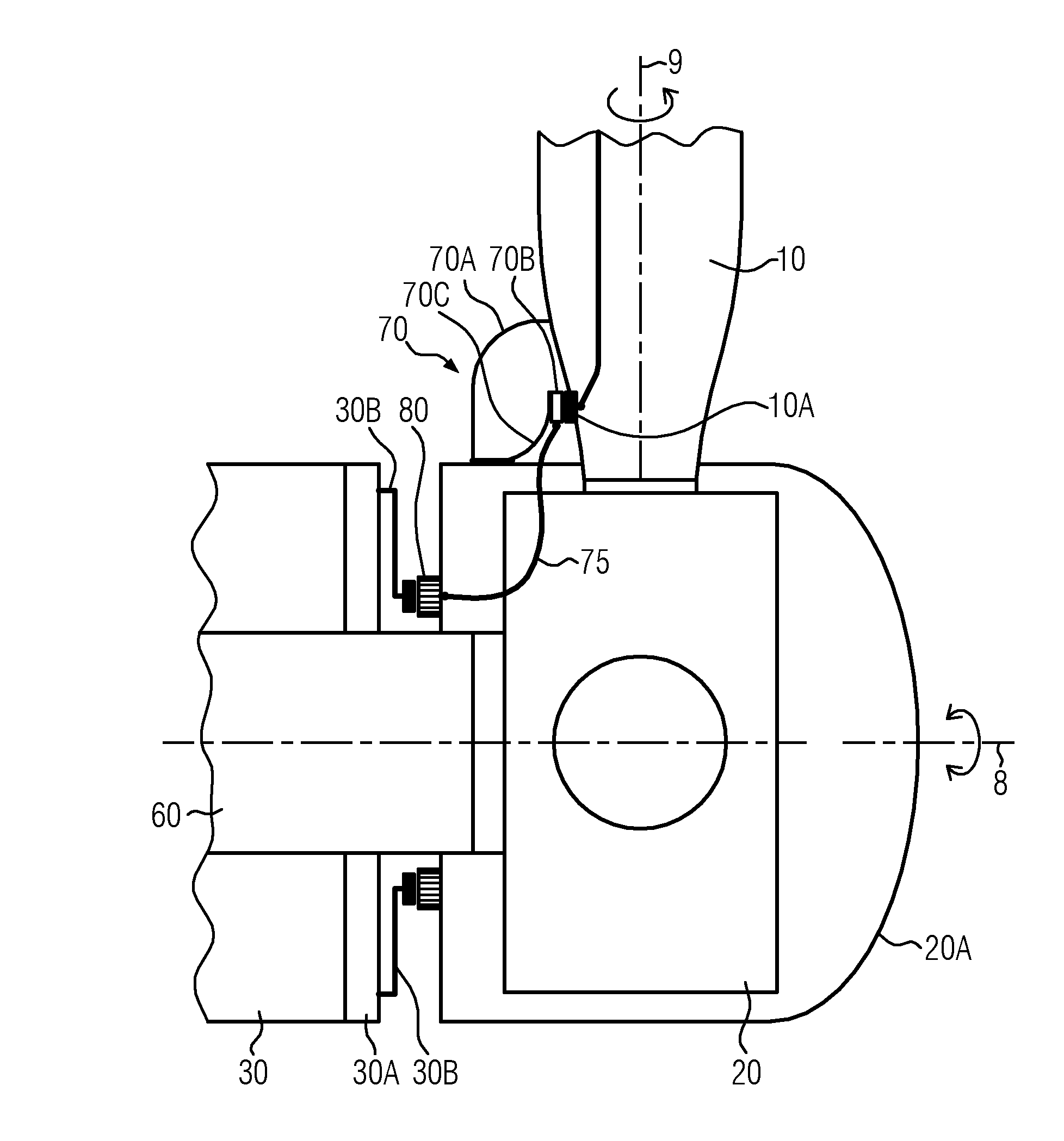
[0042]This invention has been made in order to provide a lightning current transfer system which can be used for wind turbines which are larger than the previous wind turbine constructions. In such larger wind turbines, the blades and the hub are increased in size so that the part of the lightning current transfer unit which is responsible for collecting the lightning current from the root of the blade rotates with the hub beyond the perimeter of the nacelle. Moreover, this invention has been made in order to allow at least partially the usage of lightning current transfer units according to the state-of-the-art. Moreover, all parts of the lightning current transfer unit of this invention shall be exchangeable in-situ and shall also reduce wear due to the lightning current.

[0043]FIG. 5 gives an overview of the lightning current transfer system according to the present invention. In FIG. 5, reference numeral 20 designates a hub, reference numeral 10 designates a blade, reference nume...


PUM


Abstract

The present invention relates to a lightning current transfer system (100) adapted for usage in a wind turbine (W) having a hub (20) that is rotatably supported relative to a generator in a nacelle (30) and a plurality of blades (10) that are pivotably connected with the hub, wherein the hub (20) is covered by a spinner (20A). The lightning current transfer system (100) comprises a blade band (10A) mountable to the root of the blade (10); a lightning ring (80mountable to the spinner (20A) facing the nacelle (30); a first contact device (70) mountable to the spinner (20A) adapted for providing lightning current transfer from the blade band (10A); a connecting device (75) for connecting the first contact device (70) with the lightning ring (80); and a second contact device (30B) mountable to the nacelle (30) and adapted for providing lightning current transfer from the lightning ring (80) to ground.

Description

TECHNICAL FIELD[0001]The invention relates to a lightning current transfer system adapted for usage in a wind turbine having a hub rotatably supported relative to a generator in a nacelle of the wind turbine and a plurality of blades pivotably connected with the hub. The invention also relates to a wind turbine in which the lightning current transfer system is implemented.DESCRIPTION OF THE RELATED ART[0002]Due to their size, wind turbines are prone to lightning strikes. The height of wind turbines overshoots by far surrounding trees and buildings in order to efficiently convert wind power into electric energy. If lightning strikes the tip of a blade of a wind turbine, the current flows in an uncontrolled manner through the blade, the blade bearings, the hub, the hub bearings, the generator shaft, the generator and the tower into the ground. Due to the high current values, there is a high risk that the bearings and electrical generators are damaged by the high voltages and currents ...

Claims


Application Information

Patent Timeline
Patent Type & Authority Applications(United States)
IPC IPC(8): F03D80/30F03D1/06F03D9/00
CPCF03D80/30F03D1/065F03D9/002F03D9/25Y02E10/72F03D80/80
Inventor SOGAARD, MORTEN BAGGERHANSEN, ANDERS NIELSLYNGBY, CLAUS GRONHENRIKSEN, NIELS MARTINHAASTRUP, BENJAMINCHRISTENSEN, CARSTENCHRISTENSEN, JESPER LYKKEGAARDAHLMANN, MARTIN
Owner VESTAS WIND SYST AS
Why Eureka
Try Eureka