Phase Locked Loop with Sub-harmonic Locking Prevention Functionality

a phase lock and functionality technology, applied in the field of phase lock loops, can solve problems such as leakage current problems, sub-harmonic locking, and increase the cost of dies

Active Publication Date: 2016-09-01
LATTICE SEMICON CORP
View PDF13 Cites 4 Cited by
  • Summary
  • Abstract
  • Description
  • Claims
  • Application Information

AI Technical Summary

Benefits of technology

[0019]Embodiments also relate to a non-transitory computer-readable medium storing a digital representation of the PLL tha...

Problems solved by technology

Type-II PLL typically uses a large capacitor for improving stability of the loop, which increases the die cost and also causes leakage current issues as the technology scales down to deep sub-micron CMOS process technologies.
A drawback of ...

Method used


Image

  • Phase Locked Loop with Sub-harmonic Locking Prevention Functionality
  • Phase Locked Loop with Sub-harmonic Locking Prevention Functionality
  • Phase Locked Loop with Sub-harmonic Locking Prevention Functionality

Examples


Embodiment Construction

[0028]The Figures (FIGS.) and the following description relate to various embodiments by way of illustration only. It should be noted that from the following discussion, alternative embodiments of the structures and methods disclosed herein will be readily recognized as viable alternatives that may be employed without departing from the principles discussed herein. Reference will now be made in detail to several embodiments, examples of which are illustrated in the accompanying figures. It is noted that wherever practicable similar or like reference numbers may be used in the figures and may indicate similar or like functionality.

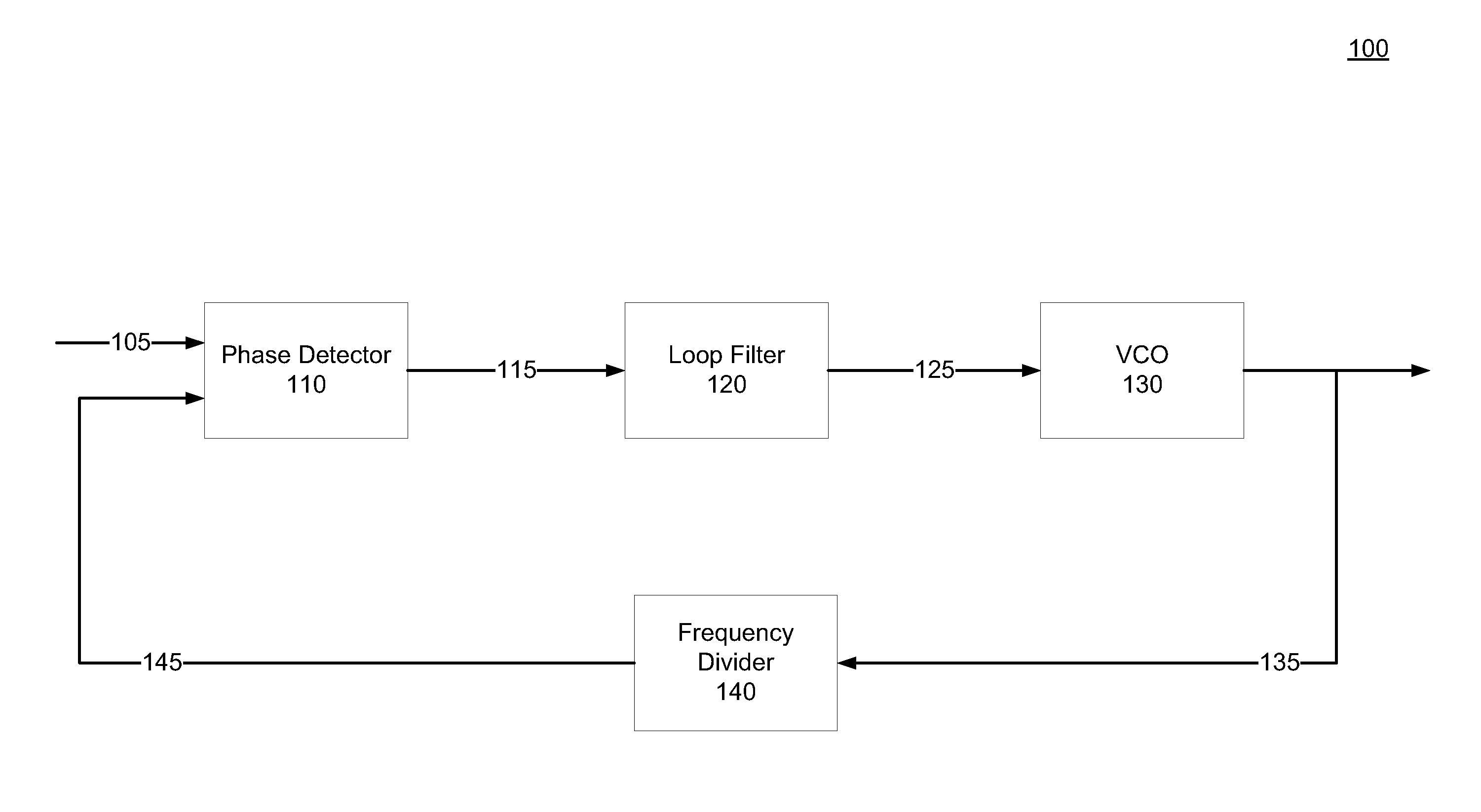
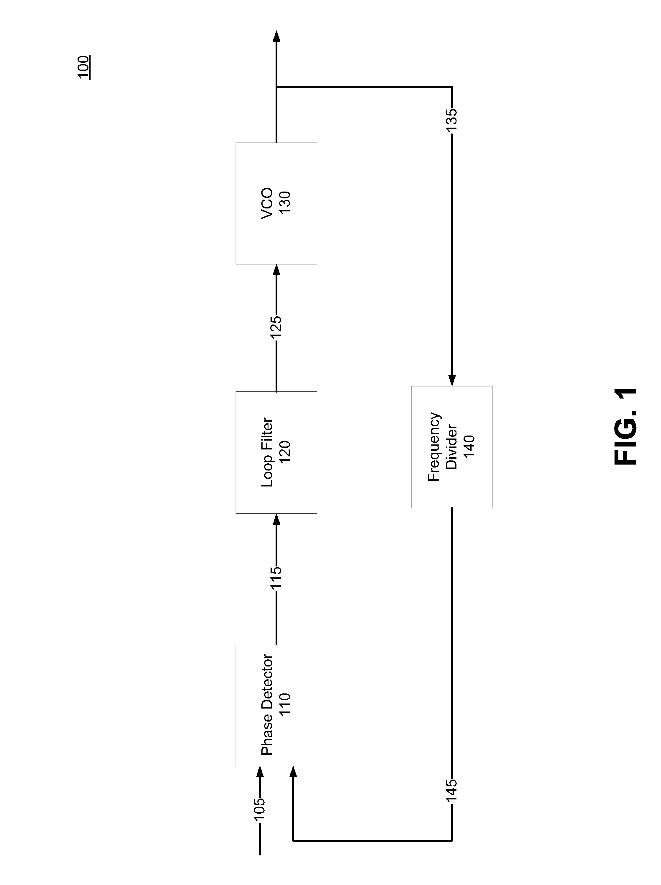
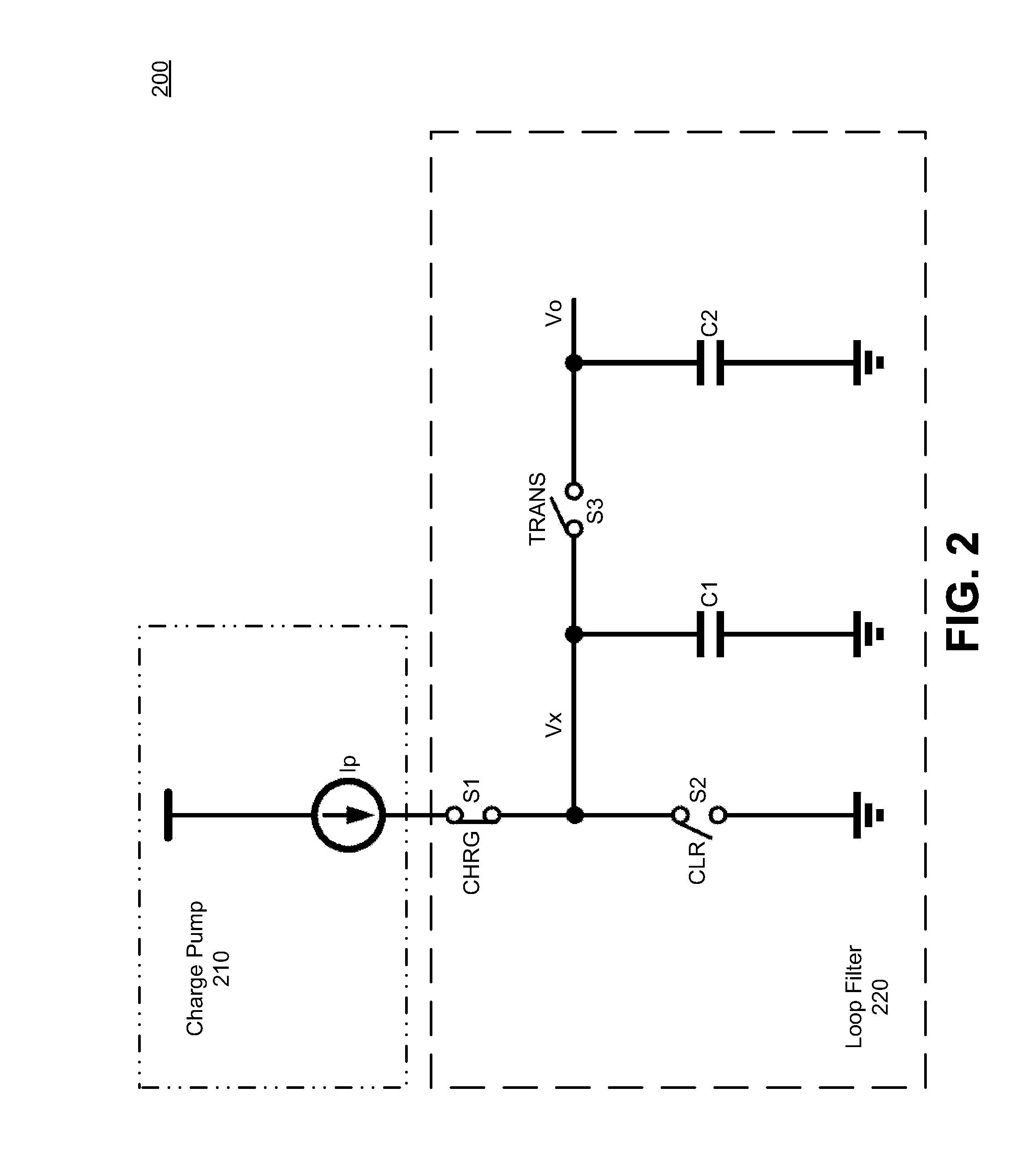
[0029]Embodiments of the present disclosure relate to type-I phase locked loops (PLLs) that do not lock at a sub-harmonic frequency of an oscillator output signal by controlling timing of charging or discharging of one or more capacitors in the PLLs. A phase frequency detector (PFD) of a type-I PLL can prevent sub-harmonic locking of the PLL by generating a...


PUM


Abstract

Embodiments relate to type-I PLLs that do not lock at a sub-harmonic frequency of a reference clock signal by controlling timing of charging or discharging of one or more capacitors in the PLLs. A phase frequency detector (PFD) of a type-I PLL can prevent sub-harmonic locking by generating a clear output signal to cause a sampling capacitor of PLL's loop filter to discharge only during a time period when the sampling capacitor is not being charged. For example, the PFD can include a gating element to control the time during which the clear output signal is generated. By ensuring that the sampling capacitor is not discharged during a time period while it is being charged, the PLL's voltage-controlled oscillator is controlled to oscillate at an intended frequency rather than at a sub-harmonic of the intended frequency.

Description

BACKGROUND[0001]1. Field of the Disclosure[0002]This disclosure pertains in general to phase locked loops (PLLs) and more particularly to a sample and reset type-I PLL.[0003]2. Description of the Related Art[0004]PLLs are widely employed in radio, telecommunications, computers, and other electronic applications. They can be used to demodulate a signal, recover a signal from a noisy communication channel, generate a stable frequency at multiples of an input frequency (frequency synthesis), or distribute precisely timed clock pulses in digital logic circuits such as microprocessors. Since a single integrated circuit can provide a complete PLL functionality, PLLs are widely used in modern electronic devices, with output frequencies ranging from a few hertz up to many gigahertz.[0005]PLLs can be implemented as either a type-I PLL or a type-II PLL. Type-II PLL typically uses a large capacitor for improving stability of the loop, which increases the die cost and also causes leakage curren...

Claims


Application Information

Patent Timeline
IPC IPC(8): H03L7/089H03L7/18H03L7/099
CPCH03L7/0891H03L7/18H03L7/099H03L7/089H03L7/093H03L2207/14
Inventor LUO, KEXINRUI, YANLU, SHAOYONGYIN, RUISHEN, YU
Owner LATTICE SEMICON CORP
Why Eureka
Try Eureka