Check patentability & draft patents in minutes with Patsnap Eureka AI!

Hydroformylation process

a technology of hydroformylation and olefin, which is applied in the direction of organic compounds/hydrides/coordination complex catalysts, physical/chemical process catalysts, organic chemistry, etc., can solve the problems of losing valuable reactants, not economical, and inability to prevent inerts

Active Publication Date: 2016-09-08
THE DOW CHEM CO +1
View PDF5 Cites 0 Cited by
  • Summary
  • Abstract
  • Description
  • Claims
  • Application Information

AI Technical Summary

Benefits of technology

The patent text says that recycling the vent stream does not lead to the buildup of hydrocarbons in the process. This is a technical improvement that helps to manage the flow of materials in the system.

Problems solved by technology

Unfortunately, venting these inerts also tends to lose valuable reactants, such as olefin.
It is not economical to send catalyst-containing streams containing some of the most common hydroformylation ligands, such as triphenylphosphine, to the syngas stripper, since at the bottom of the stripping column the catalyst will be exposed to elevated CO partial pressure and elevated temperature in the absence of olefin, thereby causing catalyst deactivation.
The above schemes involve complex, expensive designs.

Method used


Image

  • Hydroformylation process
  • Hydroformylation process
  • Hydroformylation process

Examples


examples 1-4

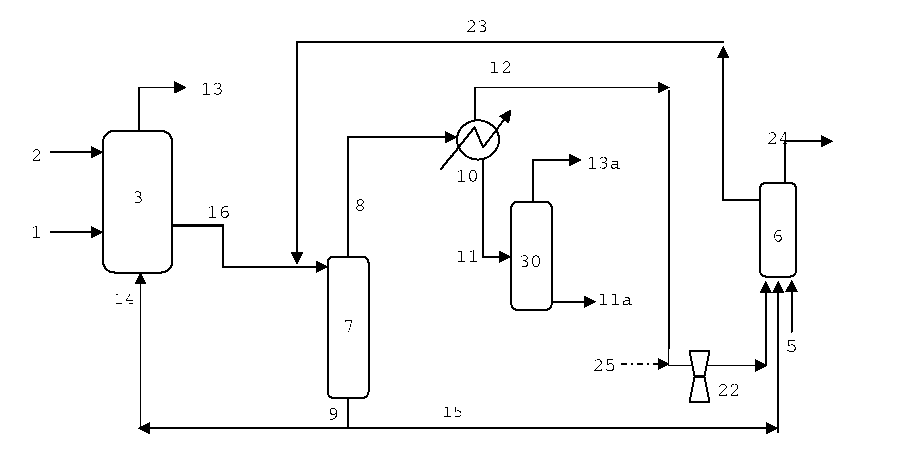
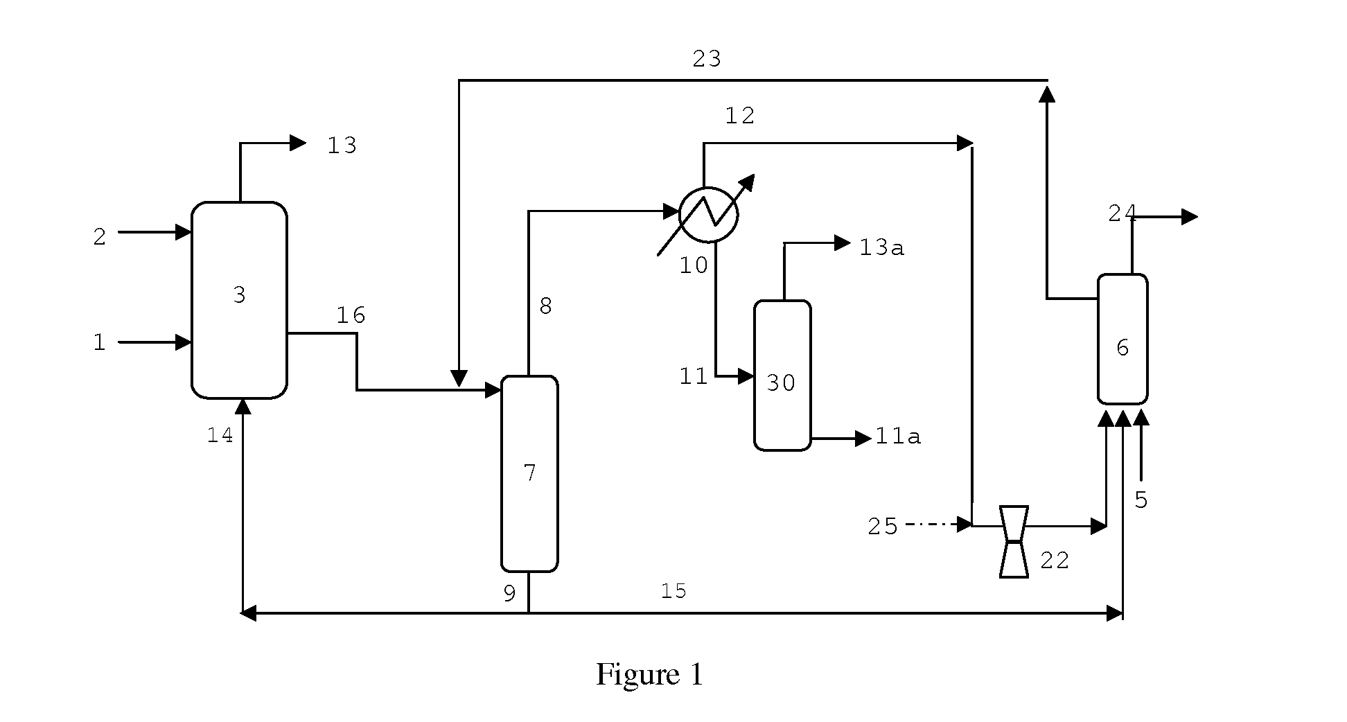
[0117]An Oxo reaction system of the invention as depicted in FIG. 1 is modeled using ASPEN Plus Dynamics™ process simulation software. The reaction conditions are those of C.E. A, but the process configuration is different. The system comprises a primary CSTR (R1), having the same volume as a CSTR of C.E. A, and a smaller, secondary CSTR (R2). A vent stream from the stabilizer column (13a) is fed via line (25) to the compressor (22).

[0118]The basis for the modeling the reactor control system is as follows:[0119]1) The Oxo reaction rate is directly proportional to rhodium concentration at constant temperature[0120]2) Rhodium concentration in each reactor is a function of the recycle catalyst mass flow rate and recycle rhodium concentration fed to each reaction. The liquid volume in each reactor is constant.[0121]3) The effects of items 1 and 2 combine so the oxo reaction rate is a function of the recycle catalyst feed rate and recycle catalyst rhodium concentration.[0122]4) Since pro...


PUM

PropertyMeasurementUnit
temperaturesaaaaaaaaaa

Abstract

A multi-reactor hydroformylation process wherein a common product-catalyst separation zone is employed.

Description

BACKGROUND OF THE INVENTION[0001]The invention relates to a process for the hydroformylation of olefins to produce aldehydes.[0002]A number of hydroformylation processes involve the further processing of vent streams from hydroformylation reactors. The purpose of the vent streams is to prevent the accumulation of inert impurities, such as N2, CO2, Ar, CH4 and hydrocarbons, by purging them from the process. The inerts may get into the process as impurities in the feeds. These are generally vented prior to the product-catalyst separation zone to reduce the load on the separation systems. Unfortunately, venting these inerts also tends to lose valuable reactants, such as olefin.[0003]There have been a number of disclosures teaching how to recover and recycle the olefin contained in these vents. Examples of these vent reactor processes are disclosed in GB 1,387,657 and U.S. Pat. Nos. 4,593,127, 5,105,018, 5,367,106, 5,675,041, 6,482,992, 6,969,777 and U.S. Pat. No. 7,405,329. Each proces...

Claims


Application Information

Patent Timeline
Patent Type & Authority Applications(United States)
IPC IPC(8): C07C45/50B01J31/24C07C45/78
CPCC07C45/50C07C45/78B01J2531/822B01J2231/321B01J31/24C07C47/02
Inventor MILLER, GLENN A.GILES, JASON F.COX, IRVIN B.
Owner THE DOW CHEM CO
Features
  • R&D
  • Intellectual Property
  • Life Sciences
  • Materials
  • Tech Scout
  • Unparalleled Data Quality
  • Higher Quality Content
  • 60% Fewer Hallucinations
Learn More