Turbine rotor blade

a technology of turbine rotor blades and turbine blades, which is applied in the field of turbine systems, can solve the problems of reducing the overall system efficiency, particularly difficult cooling of airfoil tips,

Active Publication Date: 2016-09-08
GENERAL ELECTRIC CO
View PDF5 Cites 8 Cited by
  • Summary
  • Abstract
  • Description
  • Claims
  • Application Information

AI Technical Summary

Problems solved by technology

Nevertheless, airfoil tips are particularly difficult to cool since they are located directly adjacent to the turbine shroud and are heated by the hot combu

Method used


Image

  • Turbine rotor blade
  • Turbine rotor blade
  • Turbine rotor blade

Examples


Embodiment Construction

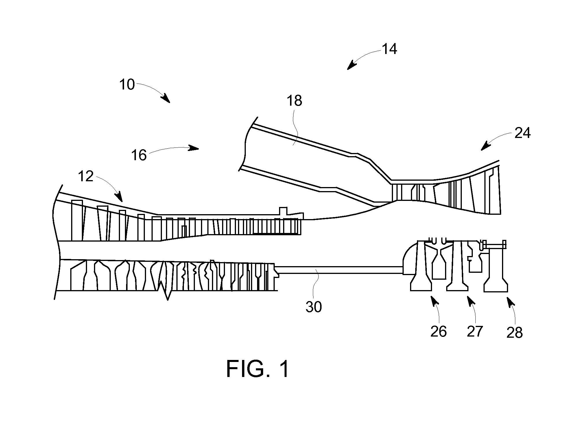
[0018]Referring to FIG. 1, a turbine system, such as a gas turbine engine 10, constructed in accordance with an exemplary embodiment of the present invention is schematically illustrated. The gas turbine engine 10 includes a compressor section 12 and a plurality of combustor assemblies arranged in a can annular array, one of which is indicated at 14. The combustor assembly is configured to receive fuel from a fuel supply (not illustrated) and a compressed air from the compressor section 12. The fuel and compressed air are passed into a combustor chamber 18 and ignited to form a high temperature, high pressure combustion product or air stream that is used to drive a turbine 24. The turbine 24 includes a plurality of stages 26-28 that are operationally connected to the compressor 12 through a compressor / turbine shaft 30 (also referred to as a rotor).

[0019]In operation, air flows into the compressor 12 and is compressed into a high pressure gas. The high pressure gas is supplied to the...


PUM


Abstract

A turbine rotor blade includes a tip portion having a pressure tip wall and a suction tip wall, a tip leading edge and a tip trailing edge. Also included is a squealer cavity at least partially defined by the pressure tip wall and the suction tip wall. Further included is at least one hole defined by the suction tip wall, the at least one hole configured to bleed a cooling flow out of the squealer cavity into a hot gas path to reduce pressure within the squealer cavity. Yet further included is a main body having a suction side wall and a pressure side wall each extending from a root portion of the turbine rotor blade to the tip portion.

Description

BACKGROUND OF THE INVENTION[0001]The subject matter disclosed herein relates to turbine systems and, more particularly, to a turbine rotor blade with enhanced cooling of a tip portion thereof.[0002]In a gas turbine engine, air pressurized in a compressor is used to combust a fuel in a combustor to generate a flow of hot combustion gases, whereupon such gases flow downstream through one or more turbines so that energy can be extracted therefrom. In accordance with such a turbine, generally, rows of circumferentially spaced turbine rotor blades extend radially outwardly from a supporting rotor disk. Each blade typically includes a dovetail that permits assembly and disassembly of the blade in a corresponding dovetail slot in the rotor disk, as well as an airfoil that extends radially outwardly from the dovetail and interacts with the flow of the working fluid through the engine.[0003]The airfoil has a generally concave pressure side and generally convex suction side extending axially ...

Claims


Application Information

Patent Timeline
IPC IPC(8): F01D5/20F02C3/04F01D5/18
CPCF01D5/20F01D5/18F02C3/04F05D2220/32F05D2240/35F05D2260/20F05D2250/121F05D2250/141F05D2240/307F01D5/147F01D5/16
Inventor CHOUHAN, ROHITJAISWAL, SHASHWAT SWAMI
Owner GENERAL ELECTRIC CO
Why Eureka
Try Eureka