Swaged collar and swaged nut

Inactive Publication Date: 2016-09-08
NEWFREY
View PDF15 Cites 2 Cited by
  • Summary
  • Abstract
  • Description
  • Claims
  • Application Information

AI Technical Summary

Benefits of technology

[0043]According to the present invention, when the tip portion is buckled and attached to a resin part, the swaged collar buckles in a fixed shape, without variability in axial symmetry, and abnormal buckling is less likely

Problems solved by technology

In general, when a resin part is fastened to an attached-to member with a bolt or the like, there is a risk of deformation or damage to the resin part, such as cracking.
However, in both the method for attaching a swaged collar using a press and the method for attaching a swaged collar using a tool, the swaged collar is buckled and attached, so abnormal buckling, such as when the swaged collar slopes in one direction when attached, can easily occur.
There is also a tendency for shape variations to occur after buckling large numbers of swaged collars, making it difficult to obtain a constant shape.
Hence, the problem arises that after buckling and attachment of the swaged collar, the inside shape does not form a circle, and the center axis of the inside diameter becomes offset from that of the outside diameter.
When the inside diameter fails to form a circle and the center axes of the inside and outside diameters are offset after buckling, a bolt cannot be inserted, and atta

Method used


Image

  • Swaged collar and swaged nut
  • Swaged collar and swaged nut
  • Swaged collar and swaged nut

Examples


first embodiment

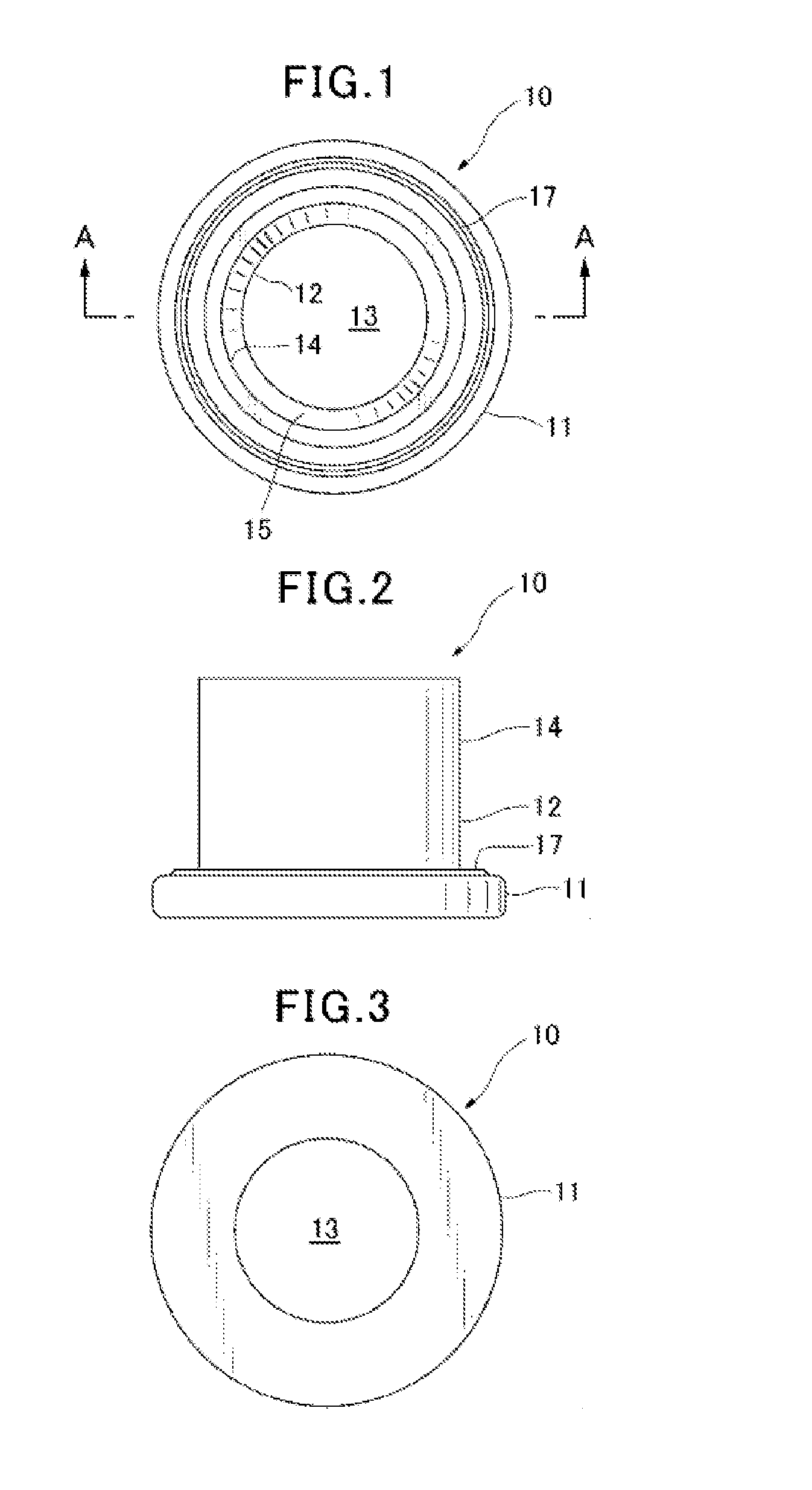
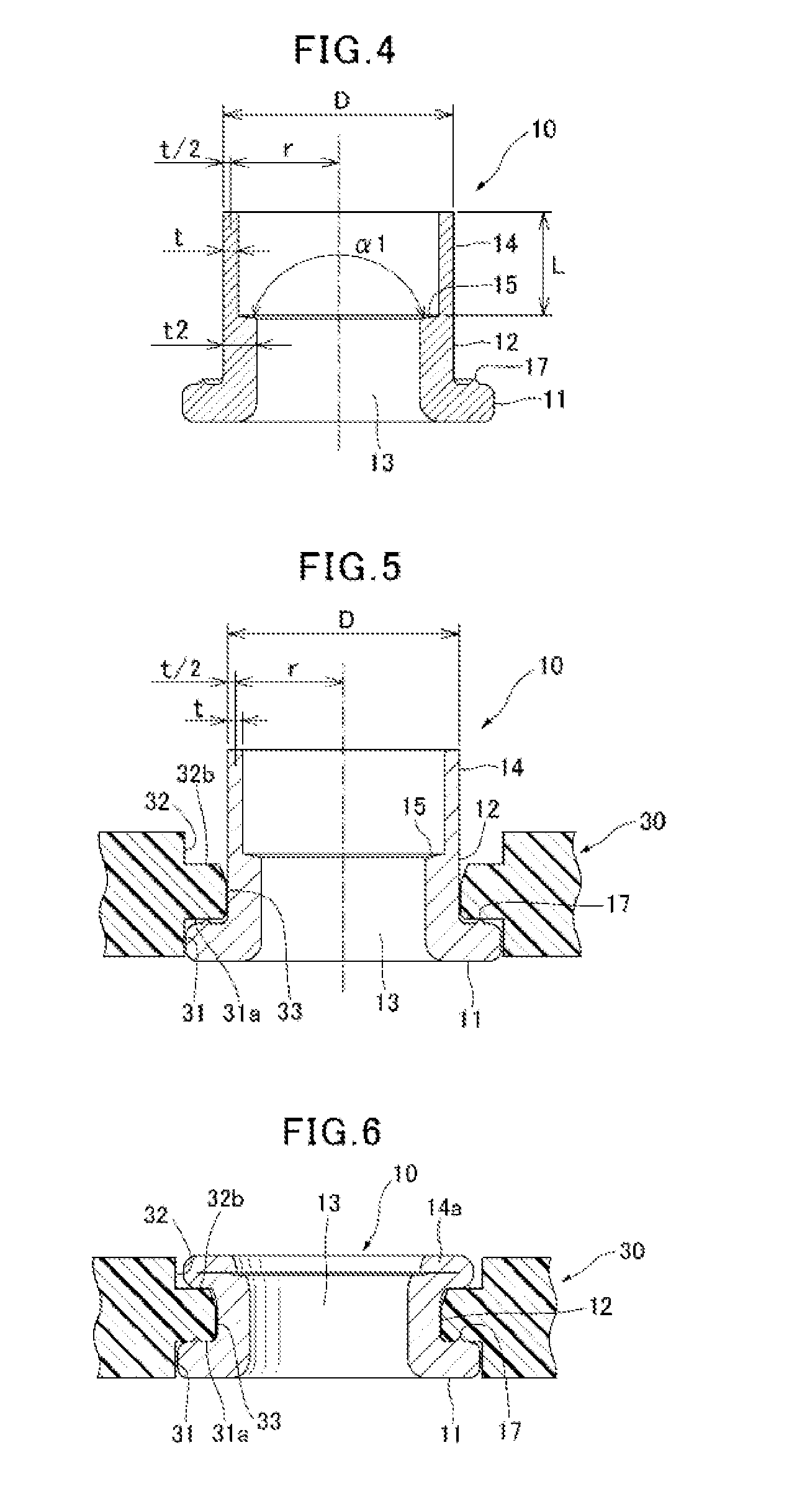
[0063]FIG. 1 is a top plan view of a swaged collar 10 in the invention. FIG. 2 is a front elevation; FIG. 3 is a bottom plan view; FIG. 4 is a cross section along line A-A in FIG. 1. FIG. 5 is a cross section showing the swaged collar 10 of FIG. 1 set into the resin part 30. FIG. 6 is a cross section showing the thin-walled portion 14 of the swaged collar 10, buckled to become buckled portion 14a, and attached to the resin part 30.

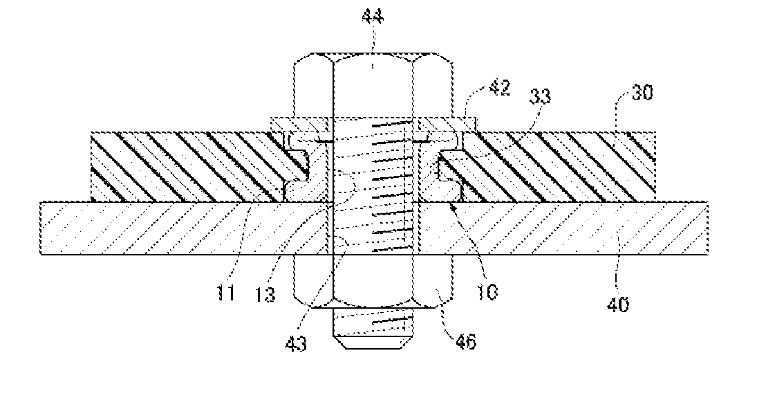
[0064]FIG. 7 is a cross section of a portion showing the state wherein a resin part 30, to which a swaged collar 10 is attached, is affixed to the attached-to member 40 using a bolt 44 and a nut 46.

[0065]In the explanation of the first embodiment, the top sides of FIGS. 4 through 7 correspond to the up direction.

[0066]The swaged collar 10 comprises a cylindrical sleeve and a flange 11, formed at one end of the sleeve, with a larger diameter than the sleeve. The sleeve has a thick-walled portion 12 with thick walls adjacent to flange 11, and a thin-walled p...

second embodiment

[0089]A projecting portion 17 extending in the circumferential direction is placed on the surface of the thick-walled portion 12 side of the flange 11. When a swaged collar 10 is attached to a resin part 30, the projecting portion 17 bites into the surface around the mounting hole 33 in the resin part 30, affixing it so that the swaged collar 10 does not move relative to the resin part 30. The projecting portion 17 may be one which extends outward in the radial direction, as in the second embodiment described below.

[0090]FIG. 5 is a cross section showing the first embodiment swaged collar 10 set into the resin part 30.

[0091]A mounting hole 33 is formed in the resin part 30. The inside diameter of the mounting hole 33 is either equal to or slightly larger than the outside diameter D of the sleeve (thick-walled portion 12 and thin-walled portion 14).

[0092]A countersunk hole-shaped indentation 31 is disposed to house the flange 11 of the swaged collar 10 at the bottom portion of mounti...

third embodiment

[0153]According to the invention, when a thin-walled portion 14 of the swaged collar 10′ is buckled and attached to a resin part, the thin-walled portion 14 is axisymmetrically expanded to a “V” shape cross section in the axial direction, and the buckled portion assumes a simple shape. Therefore, the inside shape of the swaged collar buckled portion has a certain shape similar to the oval of the original thin-walled portion 14, and there is no offset between the center axes of the inside and outside diameters of the buckled portion.


PUM


Abstract

The self-locking collar comprises a sleeve having a thick wall portion and a thin wall portion which has a thinner wall than the thick wall portion and a step portion between the thick wall portion and the thin wall portion; and a flange adjacent the thick wall portion of the sleeve. A through hole penetrates through the flange and the sleeve. The sleeve is inserted into a mounting hole of a resin component, the thin wall portion is collapsed to form a collapsed portion, and the resin component is sandwiched between the flange and the collapsed portion. The outer diameter of the thin wall portion is D, the wall thickness is t, the length is L, the Poisson ratio is γ, and:
r=(D-t)/2;m=Lπ4r2t212(1-γ2);and1.2<m<1.8

Description

CROSS-REFERENCE TO RELATED APPLICATIONS[0001]This application is a continuation of PCT Application No. PCT / JP2014 / 068728, filed Jul. 14, 2014 which claims priority from Japanese Patent Application No. 2013-242006, filed on Nov. 22, 2013, the disclosures of which are incorporated herein by reference.BACKGROUND OF THE INVENTION[0002]The present invention pertains to a metal swaged collar and swaged nut for attachment to a resin part. In particular, it pertains to a metal swaged collar and swaged nut with which, when the tip portions of a metal swaged collar and swaged nut are caused to buckle during compression on to a resin part in order to prevent deformation or damage to the resin part, the shape of the inside diameter thereof is kept constant after buckling, and the outside diameter and outside diameter thereof are maintained in a concentric relationship with no skewing of their center axes.[0003]In general, when a resin part is fastened to an attached-to member with a bolt or the...

Claims


Application Information

Patent Timeline
IPC IPC(8): F16B39/02F16B19/05
CPCF16B19/05F16B39/026F16B19/08F16B35/065F16B37/065F16B37/04F16B43/00
Inventor SAKODA, KANJI
Owner NEWFREY
Why Eureka
Try Eureka