
Acoustic wave diagnostic apparatus and method of controlling same

Active Publication Date: 2016-09-08
FUJIFILM CORP
View PDF5 Cites 0 Cited by
  • Summary
  • Abstract
  • Description
  • Claims
  • Application Information

AI Technical Summary

Benefits of technology

The present invention relates to a method and apparatus for controlling the brightness of an ultrasound image. The invention aims to eliminate the effects of noise caused by pulse-width control. The apparatus includes a high-pass filter to filter out low-frequency components of the acoustic echo signal that are output from the acoustic probe. The frequency of pulses used in the brightness control device and the fan motor is set based on the velocity scale. By setting a lower boundary value to filter out noise ascribable to pulses with the first frequency, noise at the higher frequency is filtered out to prevent its display on the display screen. By setting a higher boundary value to filter out noise ascribable to pulses with the second frequency, noise at the lower portion of the velocity scale is filtered out to prevent its display on the display screen. The technical effect of the invention is to minimize the impact of noise on ultrasound diagnosis.

Problems solved by technology

With a pulsed-Doppler ultrasound diagnostic apparatus that employs a resonating-type switching power supply, there is the danger of misdiagnosis owing to the mixing of noise with a blood flowrate pattern, which is displayed on a screen, due to the switching frequency and resonant frequency.
Thus, when backlighting of the display device is controlled utilizing pulse-width control, noise 120 or 121 appears on the display screen 60 and this can bring about misdiagnosis.
In particular, since a high sensitivity is required in a continuous-wave Doppler ultrasound diagnostic apparatus used to detect weak-power backflow, noise is even more conspicuous.

Method used


Image

  • Acoustic wave diagnostic apparatus and method of controlling same
  • Acoustic wave diagnostic apparatus and method of controlling same
  • Acoustic wave diagnostic apparatus and method of controlling same

Examples


Embodiment Construction

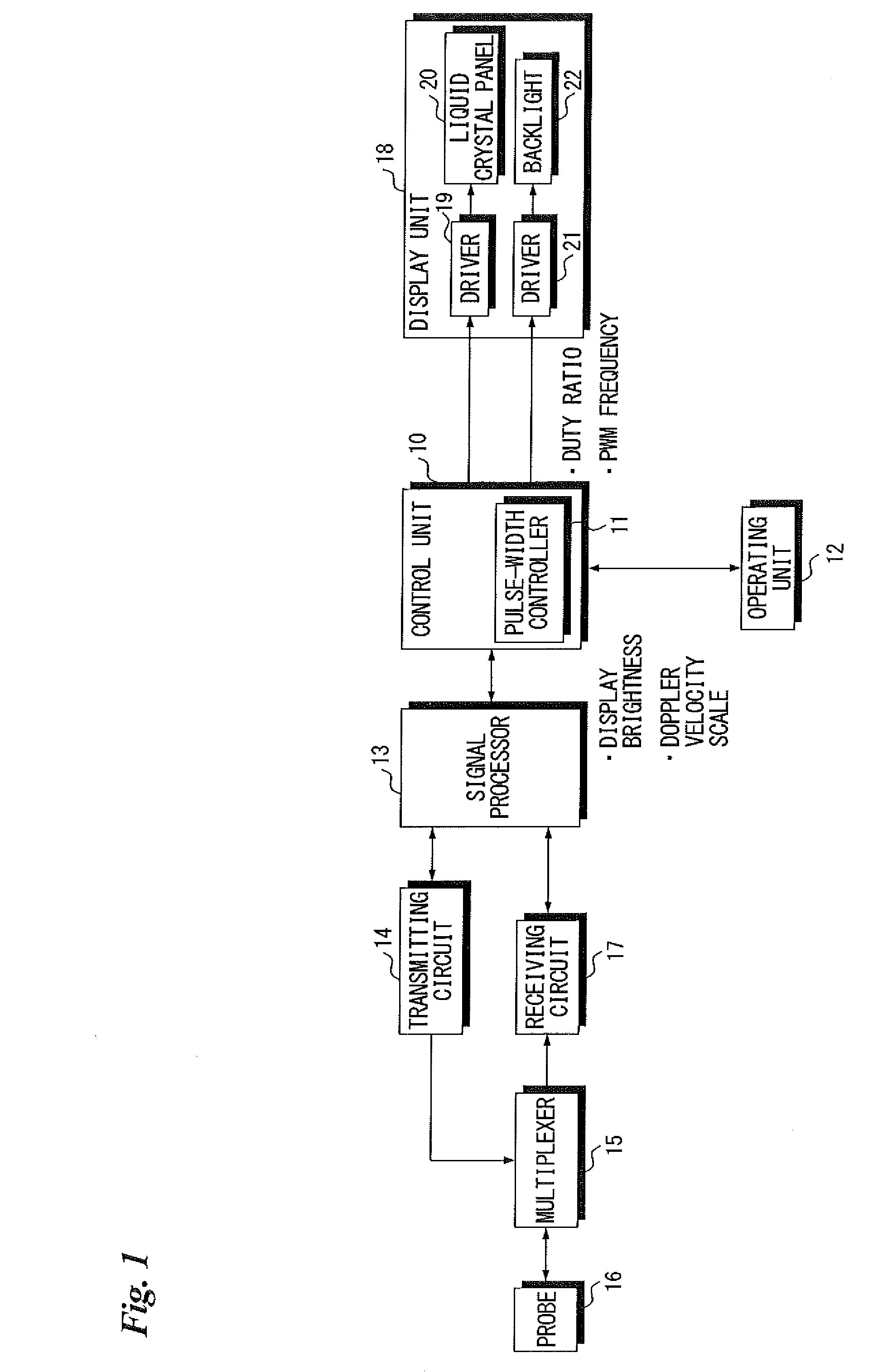
[0036]FIG. 1 is a block diagram illustrating the electrical configuration of an ultrasound diagnostic apparatus (acoustic wave diagnostic apparatus).

[0037]In this embodiment, ultrasound waves are used as the acoustic waves but the invention is not limited to ultrasound waves and it may be so arranged that acoustic waves of audible frequencies are used if an appropriate frequency is selected in accordance with the specimen (object under examination) or diagnostic conditions or the like. Further, the embodiment is not only utilized in the diagnosing of illness of a human being as the specimen but can also be utilized in a case where a moving body such as water flowing through piping or the like is investigated by generating an acoustic image (ultrasound image).

[0038]The overall operation of the ultrasound diagnostic apparatus is controlled by a control unit 10.

[0039]The ultrasound diagnostic apparatus includes a display unit 18. The display unit 18 includes a liquid crystal panel 20 o...


PUM


Abstract

If the boundary value of a velocity scale set in a case where the information indicating the velocity of the moving body is displayed on a liquid crystal panel is less than a threshold value, the frequency of pulses used in pulse-width control is set to 20 kHz in such a manner that noise ascribable to the pulses for pulse-width control will not be displayed on the liquid crystal panel. If the boundary value of the velocity scale is equal to or greater than the threshold value, then the frequency of pulses used in pulse-width control is set to 200 Hz in such a manner that noise ascribable to the pulses for pulse-width control will reside at a position remote from the information indicative of velocity.

Description

CROSS-REFERENCE TO RELATED APPLICATIONS[0001]The present application claims priority under 35 U.S.C. §119 to Japanese Patent Application No. 2015-043588 filed Mar. 5, 2015. Each of the above application(s) is hereby expressly incorporated by reference, in its entirety, into the present application.BACKGROUND OF THE INVENTION[0002]1. Field of the Invention[0003]This invention relates to an acoustic wave diagnostic apparatus and to a method of controlling such apparatus.[0004]2. Description of the Related Art[0005]With an ultrasound diagnostic apparatus, a tomographic image of a specimen is obtained by transmitting ultrasound waves toward the specimen and making use of an ultrasound echo signal that represents an ultrasound echo from the specimen. With a pulsed-Doppler ultrasound diagnostic apparatus that employs a resonating-type switching power supply, there is the danger of misdiagnosis owing to the mixing of noise with a blood flowrate pattern, which is displayed on a screen, due ...

Claims


Application Information

Patent Timeline
IPC IPC(8): G01S7/56A61B8/00G01S15/58A61B8/08
CPCG01S7/56A61B8/5207G01S15/58A61B8/546A61B8/488A61B8/461A61B8/06A61B8/5269A61B8/54G01S15/8979G01S7/52053G01S7/52077G01S7/52079G01S15/8986G01S15/8988G01S7/52096
Inventor OSHIMA, YUJIMIYACHI, YUKIYA
Owner FUJIFILM CORP
Features
  • Generate Ideas
  • Intellectual Property
  • Life Sciences
  • Materials
  • Tech Scout
  • Unparalleled Data Quality
  • Higher Quality Content
  • 60% Fewer Hallucinations
Learn More