
Control device capable of centrally managing control by grouping a plurality of systems

a control device and system technology, applied in the field of control devices, can solve the problems of high difficulty in constructing cooperative sequence programs, large amount of construction, and large amount of labor, and achieve the effect of convenient application and convenient synchronization between systems

Inactive Publication Date: 2016-09-08
FANUC LTD
View PDF6 Cites 2 Cited by
  • Summary
  • Abstract
  • Description
  • Claims
  • Application Information

AI Technical Summary

Benefits of technology

The present invention provides a control device that can communicate with multiple slave systems by controlling a master system. This makes it easier to have cooperation between systems and allows for flexibility in changing system configurations without needing to modify the sequence program of the slave systems. The control device can synchronize the actions of systems within the same system group by referring to stored information from the master system, making the synchronization process easier than in previous configurations. Additionally, if the master system is replaced or the number of systems changes, the control device can still be easily applied and used with different settings on the system group and master system for easier synchronization of systems.

Problems solved by technology

In the system shown in FIG. 18, the independence of each device is lost by the whole system being controlled by one system and even if a change of the system configuration or machining content is partial, it is necessary to rework the control of the whole sequence program, resulting in a lot of labor.
However, due to the control by the plurality of systems, it is necessary to construct the plurality of sequence programs such that when the pace of a belt conveyor is changed to 50%, the sequence programs cooperate to change the pace of each imprinter to 50% following the change of the belt conveyor, resulting in a lot of labor for the construction.
When a cooperative operation between the plurality of systems is implemented, as described above, it is necessary to cause sequence programs controlling the systems to cooperate, but the degree of difficulty of constructing cooperative sequence programs is high.
In addition, when the system configuration is changed, sequence programs that cooperate need to be reworked and thus, each time the system configuration is changed, a lot of time is needed for the work.

Method used


Image

  • Control device capable of centrally managing control by grouping a plurality of systems
  • Control device capable of centrally managing control by grouping a plurality of systems
  • Control device capable of centrally managing control by grouping a plurality of systems

Examples


first embodiment

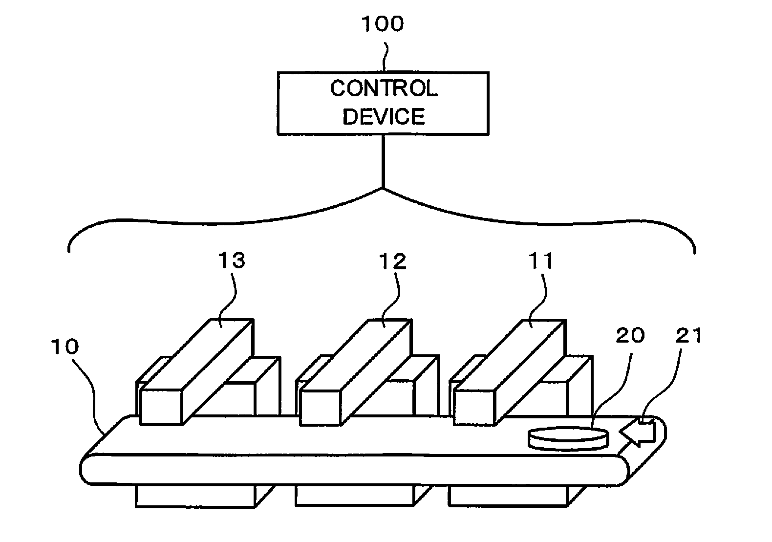
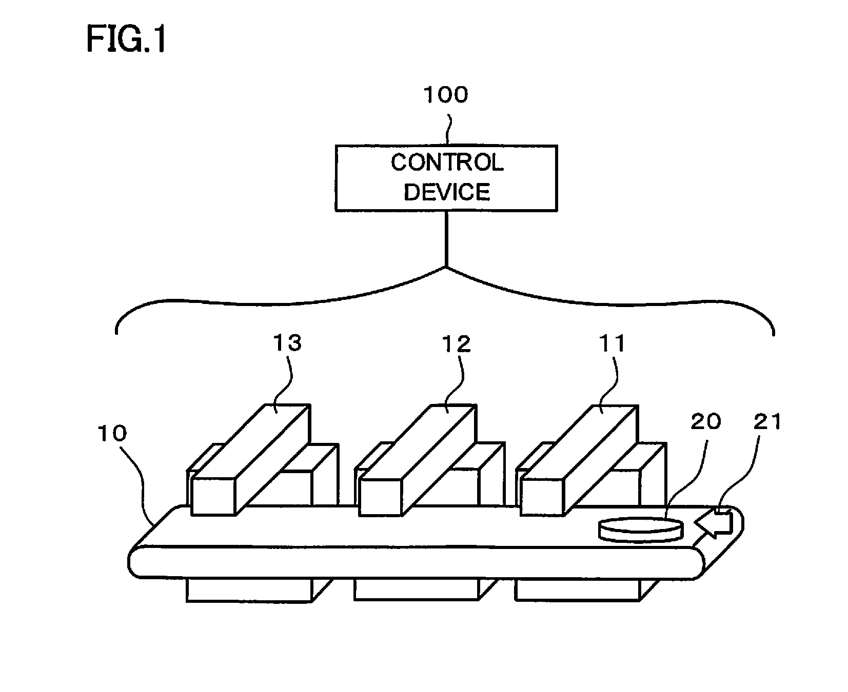
[0039]The system constituted from a belt conveyor and three imprinters shown in FIG. 1 is taken as an example. The system includes the belt conveyor 10, the first imprinter 11, the second imprinter 12, a third imprinter 13, and a control device 100 that controls the belt conveyor 10, the first imprinter 11, the second imprinter 12, and the third imprinter 13.

[0040]If, for example, the speed of the belt conveyor 10 changes in any timing, the three imprinters 11, 12, 13 also need to change the speed in synchronization with the belt conveyor 10 and if the synchronization is not implemented, imprinting in wrong positions occurs.

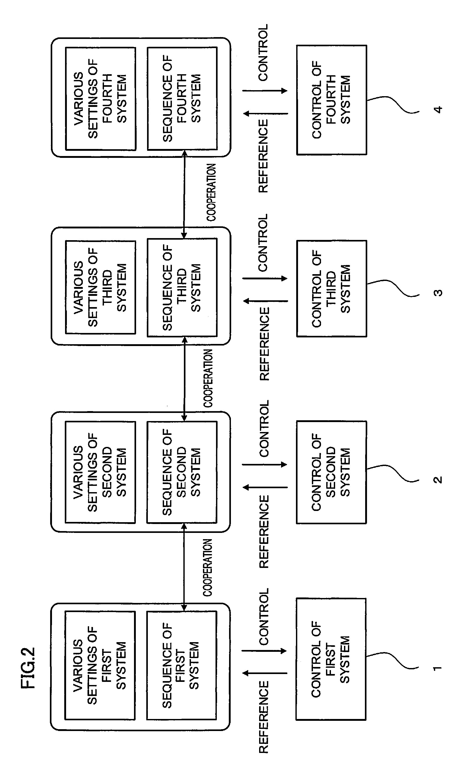
[0041]If, as shown in FIG. 2, control 1 of a first system is set to the control of the belt conveyor 10 and controls 2, 3, 4 of second to fourth systems is set to the control of the imprinters 11, 12, 13 respectively, a synchronizing speed change can be implemented by creating a sequence program that provides various settings and inter-system cooperation, but it ...

example

[0047]If the setting of an override control signal that changes the speed to 250% for execution and the setting of a parameter that limits the maximum speed to 2000 mm / min exist for a program command of moving an axis at 1000 mm / min, an operation of moving the axis at 2000 mm / min is obtained as a result of analyzing the settings.

[0048]In the case of the example shown in FIG. 6, the input / change / limitation / output described below is performed.

[0049]Program command analysis: Speed command of 1000 mm / min is input[0050]→Control signal analysis: Speed command is changed to 2500 mm / min[0051]→Control parameter analysis: Speed command is limited to 2000 mm / min[0052]→Final output: Motor is rotated at 2000 mm / min

[0053]FIG. 7 is a diagram illustrating control of a system according to the present invention. The system control is performed by a control device that controls machine tools and industrial machines. In the present invention, as a concrete implementation method of a mode in which a sla...

second embodiment

[0067]Incidentally, the machine configuration may be changed depending on the usage of machines. For example, the machine configuration shown in the first embodiment described above includes three imprinters, but the number of needed imprinters may increase or decrease due to a change of the target or the like.

[0068]FIG. 8 shows an example illustrating a situation in which machining is performed while switching the system group whenever necessary in accordance with the target and including the one belt conveyor 10 and four imprinters 11, 12, 13, 14. When, as shown in FIG. 8A, the target is a circular workpiece, the fourth imprinter 14 is not needed, but when, as shown in FIG. 8B, the target is a rectangular workpiece, the fourth imprinter 14 needs to be used. In such a case, an operator changes the setting of the system group whenever necessary in accordance with the target and deals with the situation by excluding a fifth system (fourth imprinter 14) from the system group for a cir...


PUM


Abstract

A control device selects two systems or more from a plurality of systems based on a parameter setting of a system group setting unit to set the systems as a system group, selects one system in the system group as a master system to be a reference of operation based on a parameter setting of a master system selection unit, classifies other systems in the system group as a slave system group, and controls the operation of the slave system group so as to be synchronized with the operation of the master system by referring to a program command, a control signal, and a control parameter stored in a control information storage unit as master control information.

Description

RELATED APPLICATIONS[0001]The present application claims priority to Japanese Patent Application Number 2015-040496, filed Mar. 2, 2015, the disclosure of which is hereby incorporated by reference herein in its entirety.BACKGROUND OF THE INVENTION[0002]1. Field of the Invention[0003]The present invention relates to a control device, and in particular, relates to a control device capable of centrally managing control by grouping a plurality of systems.[0004]2. Description of the Related Art[0005]FIG. 18 is a diagram illustrating a system constituted from a belt conveyor and a plurality of imprinters. The system includes a belt conveyor 10, a first imprinter 11, a second imprinter 12, and a control device (not shown) that controls the belt conveyor 10, the first imprinter 11, the second imprinter 12. The system imprints on a target 20 conveyed by the belt conveyor 10 in a moving direction 21 in a predetermined position. The running pace of the whole system depends on the belt conveyor...

Claims


Application Information

Patent Timeline
IPC IPC(8): G05B19/4155
CPCG05B2219/40007G05B19/4155G05B19/41865G05B2219/32252G05B19/4141G05B2219/50218
Inventor OONISHI, YUUKI
Owner FANUC LTD
Learn More