

Divided-wall column
a column and wall technology, applied in the field of chemical equipment, can solve the problems of affecting the use requiring relatively high energy consumption and investments, and a long time for the concept of divided wall columns, so as to simplify the design of columns and eliminate external accessory structures. , the effect of reducing the number of devices
- Summary
- Abstract
- Description
- Claims
- Application Information
AI Technical Summary
Benefits of technology
Problems solved by technology
Method used
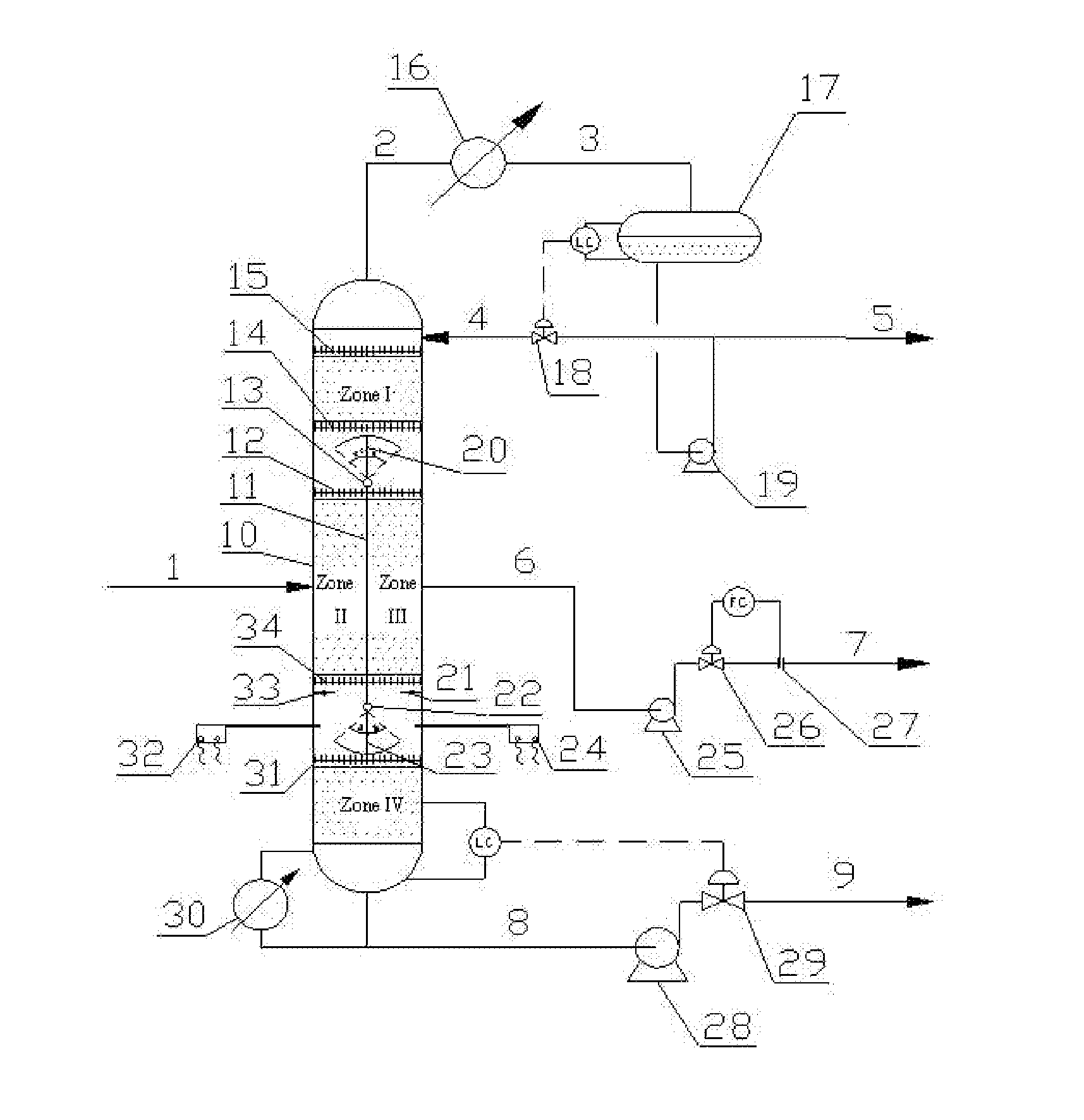
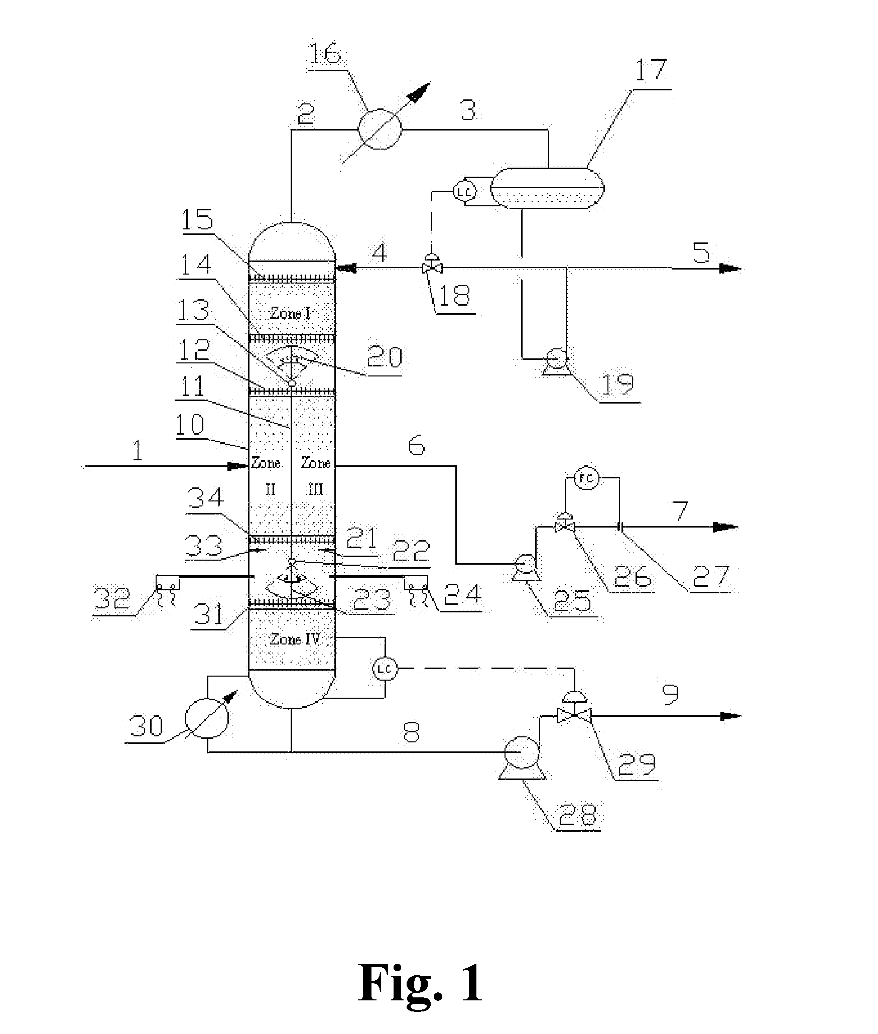
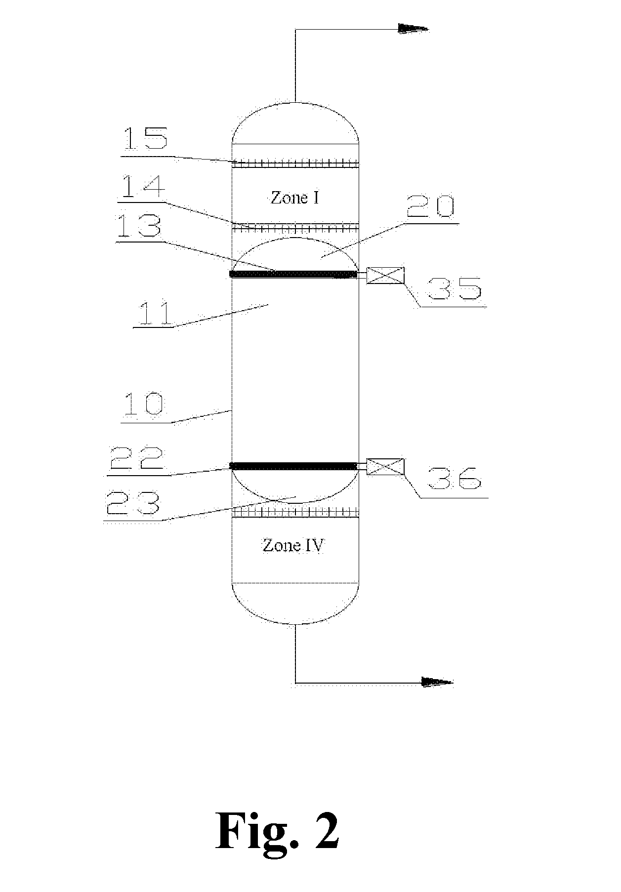
Image

Examples
example 1
[0057]A mixture of n-pentane (A), n-hexane (B), and n-heptane (C) was used as a separation system. Basic operating parameters were shown in Table 1.
TABLE 1Basic operating parametersFeed rate1000 kg / hComponents of feed material [CA, CB, CC][0.3, 0.3, 0.4]Overall reflux ratio3Overhead temperature, ° C.51Bottoms temperature, ° C.101Distribution ratio of liquids (zone II / zone IV)0.4:0.6Distribution ratio of vapors (zone II / zone IV)0.5:0.5
[0058]The parameters of a stream distribution control system were indicated in Table 2.
TABLE 2parameters of stream distribution control systemRotation angle of liquid splitter plate 20 (towards zone II)11.5°Rotation angle of vapor splitter plate 23 (towards zone IV) 8.5°Flow rate of vapor (zone II)0.75 m / sFlow rate of vapor (zone IV)0.75 m / s
[0059]The separation effects were shown in Table 3.
TABLE 3Separation effectsName ofOverheadSide-drawBottomsstreamproductproductproductPurity ofA99.9%70 ppm40 ppmconstituentB100 ppm99.9%75 ppmC 80 ppm50 ppm99.9%
example 2
[0060]Straight-run gasoline was used as the separation system. The properties of the gasoline were shown in Table 4.
TABLE 4Properties of straight-run gasolineDistillation rangeComponent(D86) / %IBP67.110%71.630%78.550%89.970%122.790%165.6FBP193.0
[0061]The basic operating parameters were shown in Table 5.
TABLE 5Basic operating parametersFeed rate1000 kg / hOverall reflux ratio2Overhead temperature, ° C.74Bottoms temperature, ° C.161Distribution ratio of liquids (zone II / zone IV)0.4:0.6Distribution ratio of vapors (zone II / zone IV)0.45:0.55
[0062]The parameters of the stream distribution control system were indicated in Table 6.
TABLE 6Parameters of stream distribution control systemRotation angle of liquid splitter plate 20 (towards zone II)11.5°Rotation angle of vapor splitter plate 23 (towards zone II)7°Flow rate of vapor (zone II)0.63 m / sFlow rate of vapor (zone IV)0.77 m / s
[0063]The separation effects were shown in Table 7.
TABLE 7Separation effectsComponentOverheadSide-drawBottoms(D86)p...
example 3
[0065]Straight-run gasoline was used as the separation system. The properties of the gasoline were shown in Table 4.
[0066]The basic operating parameters were shown in Table 8.
TABLE 8Basic operating parametersFeed rate1000 kg / hOverall reflux ratio2.5Overhead temperature, ° C.73.1Bottoms temperature, ° C.162Distribution ratio of liquids (zone II / zone IV)0.5:0.5Distribution ratio of vapors (zone II / zone IV)0.48:0.52
[0067]The parameters of the stream distribution control system were indicated in Table 9.
TABLE 9The parameters of stream distribution control systemNo liquid splitter plate was arranged.Rotation angle of vapor splitter plate 23 (towards zone II)4.5°Flow rate of vapor (zone II)0.72 m / sFlow rate of vapor (zone IV)0.78 m / s
[0068]The separation effects were shown in Table 10.
TABLE 10Separation effectsComponentOverheadSide-drawBottoms(D86)product / ° C.product / ° C.product / ° C.IBP56.883.1141.110%61.291.2144.430%63.5105.3155.350%69.8111.4160.170%75.2118.5169.990%89.1129.5181.8FBP103.4...
PUM
 Abstract
Description
Claims
Application Information