
Eureka
For R&D, Eureka makes reading and utilizing patents & technical documents easy.
Eureka AIR
Designed for self-driven R&D workflows. Generate viable solutions, solve complex R&D challenges, empower your innovation with AI.

Eureka Materials
Designed for material experts only. Revolutionize your material R&D, from search, analyze, to developing new materials.

TechResearch
Generate reliable direction feasibility study reports for your R&D in just a few steps.

TechSeek
Discover and master advanced knowledge NOW. Basics, ideas, possibilities, all at once.

TechMind
As an expert in R&D Theories, TechMind can generates customized viable solutions instantly.

TechRisk
Analyze your overall solution with one click, know your potential R&D risks in advance.

TechMonitor
Get weekly tech updates, stay abreast of the latest tech innovations and key insights.
Air conditioning system for motor vehicles
- Summary
- Abstract
- Description
- Claims
- Application Information
AI Technical Summary
Benefits of technology
Problems solved by technology
Method used
Image

Examples
first embodiment
[0050]Next, some features of the air conditioning system for motor vehicles according to the present invention will be described in detail with reference to FIGS. 3 to 5.
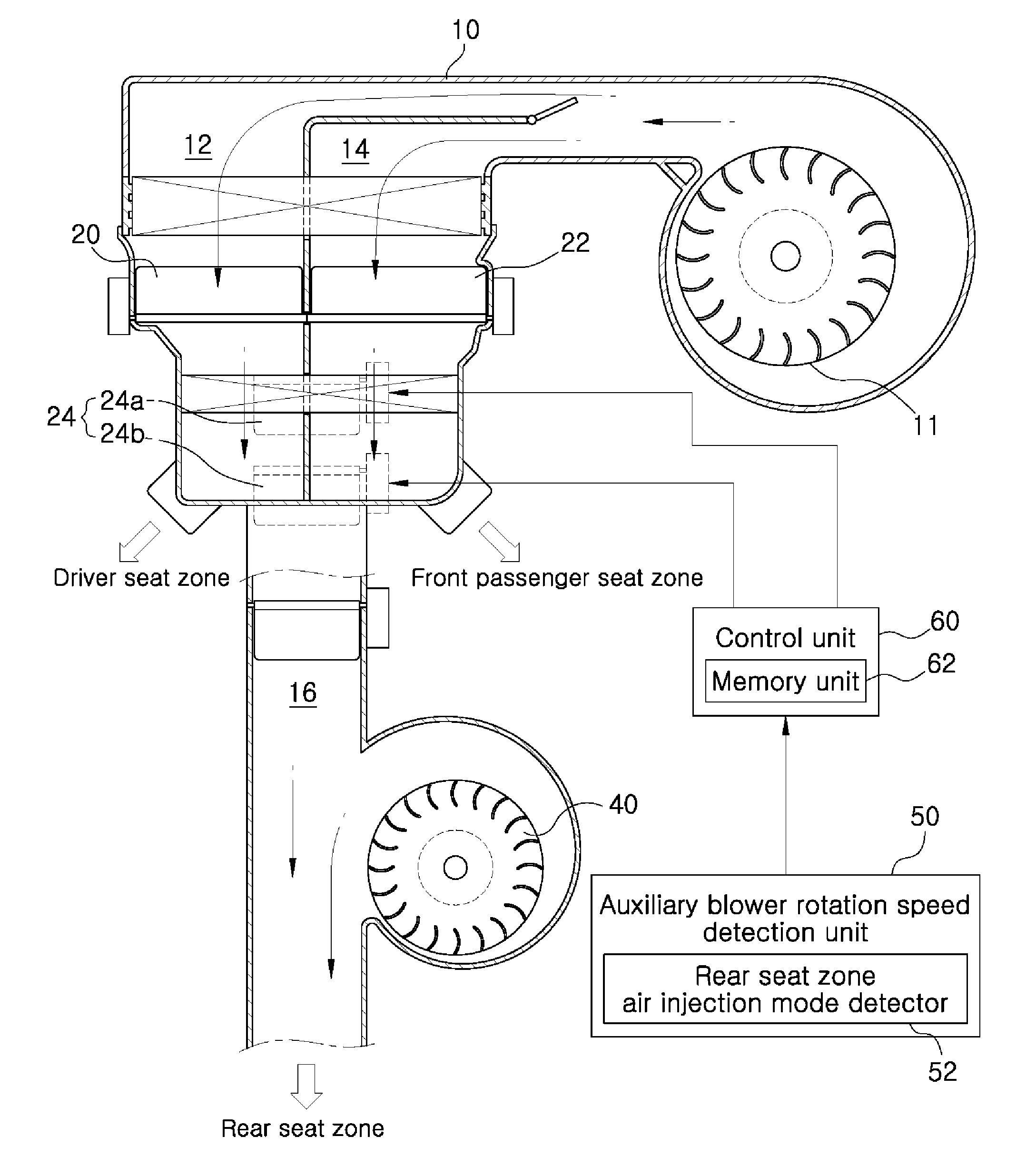
[0051]Referring first to FIGS. 3 and 4, the air conditioning system according to the present embodiment includes an auxiliary blower rotation speed detection unit 50 configured to detect a rotation speed of the auxiliary blower 40.
[0052]The auxiliary blower rotation speed detection unit 50 includes a rear seat zone air injection mode detector 52 configured to detect a rear seat zone air injection mode. The rear seat zone air injection mode detector 52 includes an injection mode adjustment switch (not shown) for a rear seat controller (not shown).
[0053]The injection mode adjustment switch is a switch for selecting one of a vent mode, a bi-level mode and a floor mode as a rear seat zone air injection mode. Upon selecting the rear seat air injection mode, it is possible for the auxiliary blower rotation speed detection...
second embodiment
[0084]The air conditioning system of the second embodiment does not include the auxiliary blower rotation speed detection unit 50 (see FIG. 4) but includes a temperature sensor 70 configured to detect the temperature of the air blown toward the auxiliary blower 40.
[0085]The temperature sensor 70 is installed in the rear seat path 16 at the upstream side of the auxiliary blower 40. The temperature sensor 70 is configured to detect the temperature of the air at the upstream side of the auxiliary blower 40 and to input detected temperature data to the control unit 60.
[0086]If the detected temperature data indicating the temperature of the air at the upstream side of the auxiliary blower 40 is inputted from the temperature sensor 70, the control unit 60 determines whether the detected air temperature is equal to or higher than the first reference temperature, namely 70 degrees C., which is pre-stored in the memory unit 62.
[0087]If the detected air temperature is equal to or higher than ...
PUM
 Abstract
Description
Claims
Application Information
 - R&D Engineer
- R&D Manager
- IP Professional
- Industry Leading Data Capabilities
- Powerful AI technology
- Patent DNA Extraction
Browse by: Latest US Patents, China's latest patents, Technical Efficacy Thesaurus, Application Domain, Technology Topic, Popular Technical Reports.
© 2024 PatSnap. All rights reserved.Legal|Privacy policy|Modern Slavery Act Transparency Statement|Sitemap|About US| Contact US: help@patsnap.com