Method and apparatus for acoustic downhole telemetry and power delivery system using transverse or torsional waves

a technology of transverse or torsional waves and power delivery system, which is applied in the field of acoustic communication and to pipes for gas and oil production, can solve the problems of greater power required for comparable operation, and achieve the effect of minimizing potential interference and improving link efficiency

Active Publication Date: 2016-09-15
RENESSELAER POLYTECHNIC INST
View PDF4 Cites 17 Cited by
  • Summary
  • Abstract
  • Description
  • Claims
  • Application Information

AI Technical Summary

Benefits of technology

[0010]This invention provides a method and apparatus for conveying power and data axially along the segments of steel pipe and casing using acoustic waves. The approach can be applied to a wide variety of other geometries including, for example, beams, and planar sheets. Acoustic waves are generated using shear-polarized piezoelectric transducers and injected into the wall of the casing using a transition piece that is acoustically coupled to the wall. This transition piece may be of the same material (e.g. steel or another metal) or of a different material than the casing and can have different shapes, including a wedge or a bar with a rectangular cross-section. The acoustic power is received using a similar structure. Multiple transmitters and / or receivers may be used to improve the efficiency of the link by taking advantage of the fact that the acoustic beam spreads as it moves away from the source. Transverse (shear-horizontal) and / or torsional wave modes are used to limit the power loss to the environment in contact with the interior and exterior wall of the casing / substrate. Higher frequencies, i.e. those well above the audio or near-audio frequency range, are used for communications to minimize the potential interference due to ambient vibrations. These frequencies may also be used for power transfer.
[0012]A preferred channel is formed by epoxying steel wedges with attached ultrasonic transducers on the exterior of a 5.2 m long steel pipe with a separation of 4.8 m. The open-ended pipe is placed into a water-filled trough for immersed experiments. The transducers are shear-mode plates which are epoxied to the wedges, producing transverse waves in the wedges and pipe wall, where the wave displacement is oriented in the circumferential direction of the pipe (effectively shear-horizontal). The channel response is measured using a vector network analyzer and it is found that the channel attenuation varies considerably with small changes in frequency. To combat the effects of this frequency selectivity, and address the power constraints, simple modulation schemes using non-coherent demodulation methods are employed for data transmission, including Chirp-On-Off keying (C-OOK). The chirp waveform is a frequency modulated wave whose frequency increases over the bit-interval (either linearly or exponentially), where the width of the chip's spectrum is specified a-priori (10 kHz in this case). The wideband nature of the chirp waveform provides resilience against nulls in the channel response while making it possible to implement a simple non-coherent receiver. The test data link is assembled using an arbitrary waveform signal generator to generate the chirp signal that is applied to the transmit transducer, a demodulator circuit consisting of a ceramic filter and logarithmic amplifier followed by a computer controlled digitizer to capture the signal from the receive transducer, with final processing and bit-decoding done via the computer.

Problems solved by technology

The power required for comparable operation is greater when the channel is immersed in water due to the additional attenuation introduced by energy loss into the water.

Method used


Image

  • Method and apparatus for acoustic downhole telemetry and power delivery system using transverse or torsional waves
  • Method and apparatus for acoustic downhole telemetry and power delivery system using transverse or torsional waves
  • Method and apparatus for acoustic downhole telemetry and power delivery system using transverse or torsional waves

Examples


Embodiment Construction

Acoustic-Electric Channels

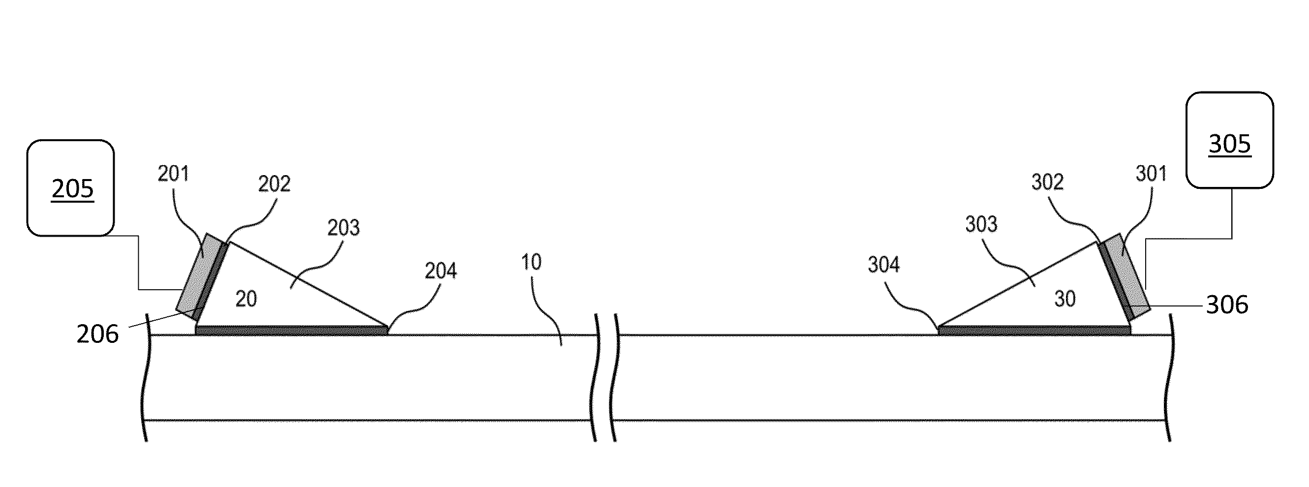
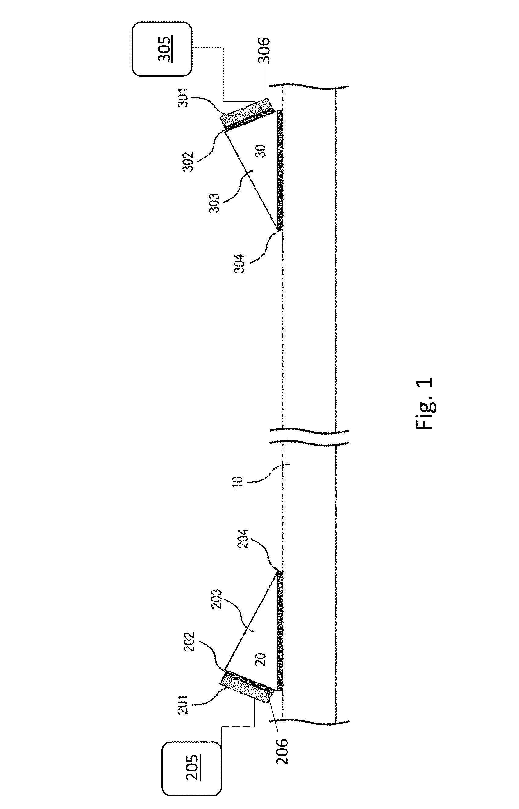
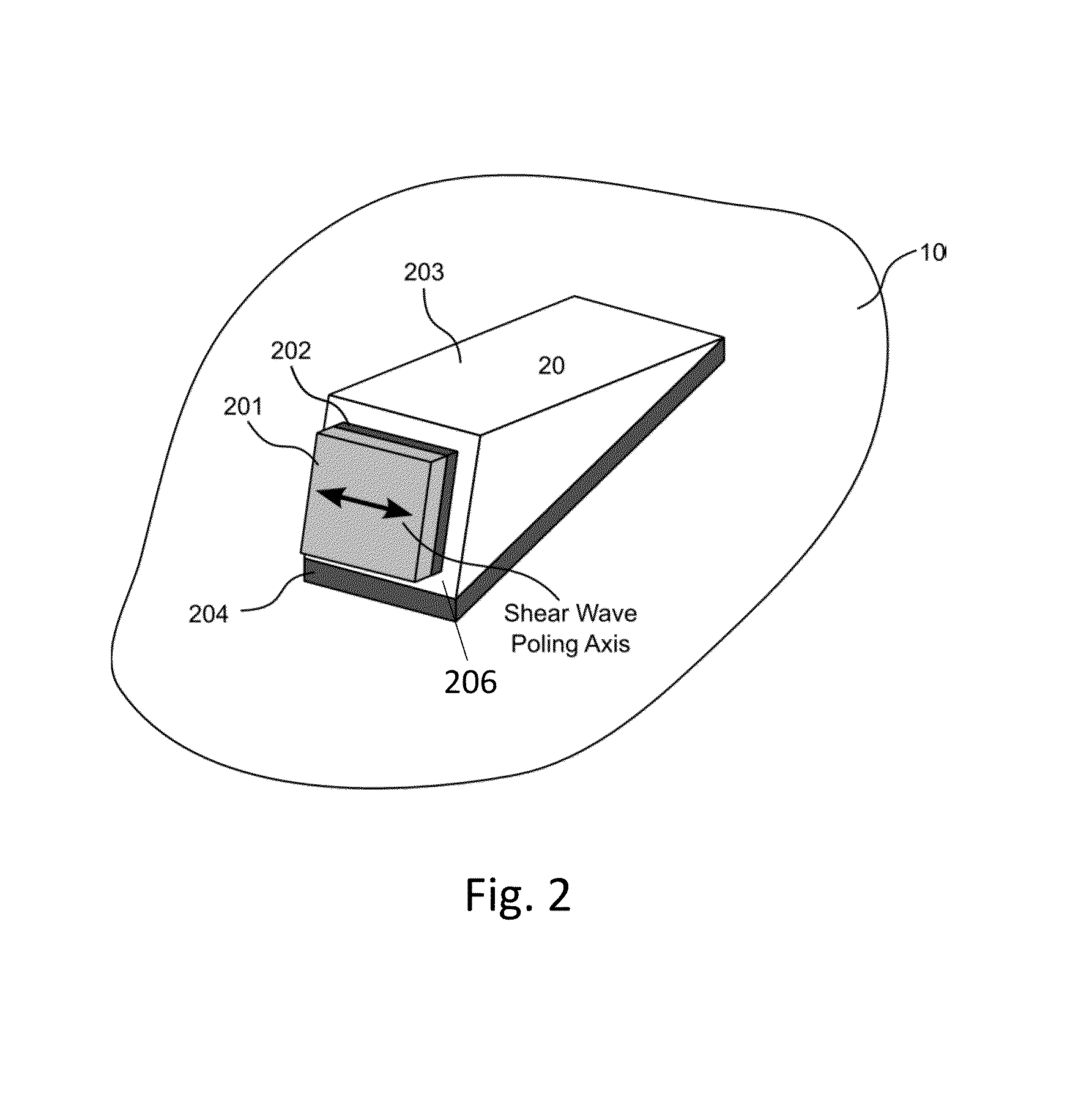
[0062]Referring now to the drawings, in which like reference numerals are used to refer to the same or similar elements, FIG. 1 schematically shows a simple acoustic electric channel for use with this invention. The channel includes a substrate 10, a transmit assembly 20, and a receive assembly 30. The assemblies depicted each include four basic components: a transducer 201,301 (e.g. a shear plate transducer), shear plate-wedge acoustic couplant 202,302, acoustic wedge 203,303 transition piece (or transition piece of alternative shape), and wedge-substrate acoustic couplant 204,304. Each transducer is linked to transmit 205 and receive 305 electronics, which may include sensors, signal processing electronics, power storage, signal transmission and reception elements, and / or other components which will vary between embodiments. FIG. 2 presents an isometric view of the transmit assembly 20, with the preferred particle displacement axis of the generated shear ...


PUM


Abstract

Methods and apparatus for transmitting power and data along a metal pipe using wideband acoustic waves. Arrangements use shear-horizontal waves, transmitting narrowband signals for power applications and wideband signals for communications having a bandwidth greater than the coherence bandwidth of the acoustic-electric channel. Chirp wave signals, direct sequence spread signals, and on-off keying are used. Acoustic-electric channels include wedges fixed to a pipe or other substrate, transducers fixed to the wedges, and electronics linked to each transducer for sending and receiving power and signals. Matching networks, rectification circuits, and non-coherent signal reception methods may be used.

Description

RELATED APPLICATION[0001]Benefit and priority are claimed to U.S. Provisional Application No. 61 / 969977, filed Mar. 25, 2014, which is fully incorporated by reference herein.BACKGROUND[0002]The present invention relates generally to the field of acoustic communication and to pipes for gas and oil production, and in particular to transducer arrangements for communicating power and data through metal substrates such as along pipes.[0003]There is growing interest in expanding the capability to measure environmental parameters such as pressure and temperature at any location within the downhole environment present in hydrocarbon wells. These wells often utilize connected steel casing segments to form isolated well sections. Multiple concentric casings of different diameters separated by annular regions may be present in some segments of the well. These casings are used to isolate some regions of the well from other sections such as, for instance, hold back the high hydrostatic pressures...

Claims


Application Information

Patent Timeline
Patent Type & Authority Applications(United States)
IPC IPC(8): E21B47/16H04B1/69H04L27/148H04B11/00H04L27/10
CPCE21B47/16H04B11/00H04B2001/6912H04L27/148H04B1/69H04L27/103H04L25/0202H04L25/0288H04L25/4902
Inventor SAULNIER, GARY J.WILT, KYLE R.LITMAN, R. BENJAMINSCARTON, HENRY A.CHAKRABORTY, SOUMYA
Owner RENESSELAER POLYTECHNIC INST
Why Eureka
Try Eureka