Method and device for monitoring a particulate filter

a technology of particulate filter and monitoring device, which is applied in the direction of temperature measurement of flowing materials, instruments, machines/engines, etc., can solve the problems of particularly perceptible delay of the particulate filter effect and reduce the amplitude of temperature fluctuations

Inactive Publication Date: 2016-09-15
ROBERT BOSCH GMBH
View PDF9 Cites 27 Cited by
  • Summary
  • Abstract
  • Description
  • Claims
  • Application Information

AI Technical Summary

Benefits of technology

[0027]In addition to the delaying effect on the temperature characteristic curve, the heat capacity of the particulate filter also has the effect of reducing the amplitude of temperature fluctuations. This reduction depends on the duration of the fluctuation. The present invention provides for a correctly installed particulate filter to be inferred if the time characteristic curve of the second exhaust-gas temperature has an amplitude that is smaller at most by a specifiable factor than the time characteristic curve of the first exhaust-gas temperature. If the particulate filter is removed, then the connecting pipe has a lower thermal mass and reduces the amplitude of temperature fluctuations only negligibly.

Problems solved by technology

The delaying effect of the particulate filter occurs particularly perceptibly in the event of a cold start of the internal combustion engine.

Method used


Image

  • Method and device for monitoring a particulate filter
  • Method and device for monitoring a particulate filter
  • Method and device for monitoring a particulate filter

Examples


Embodiment Construction

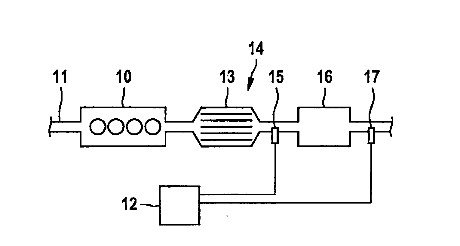
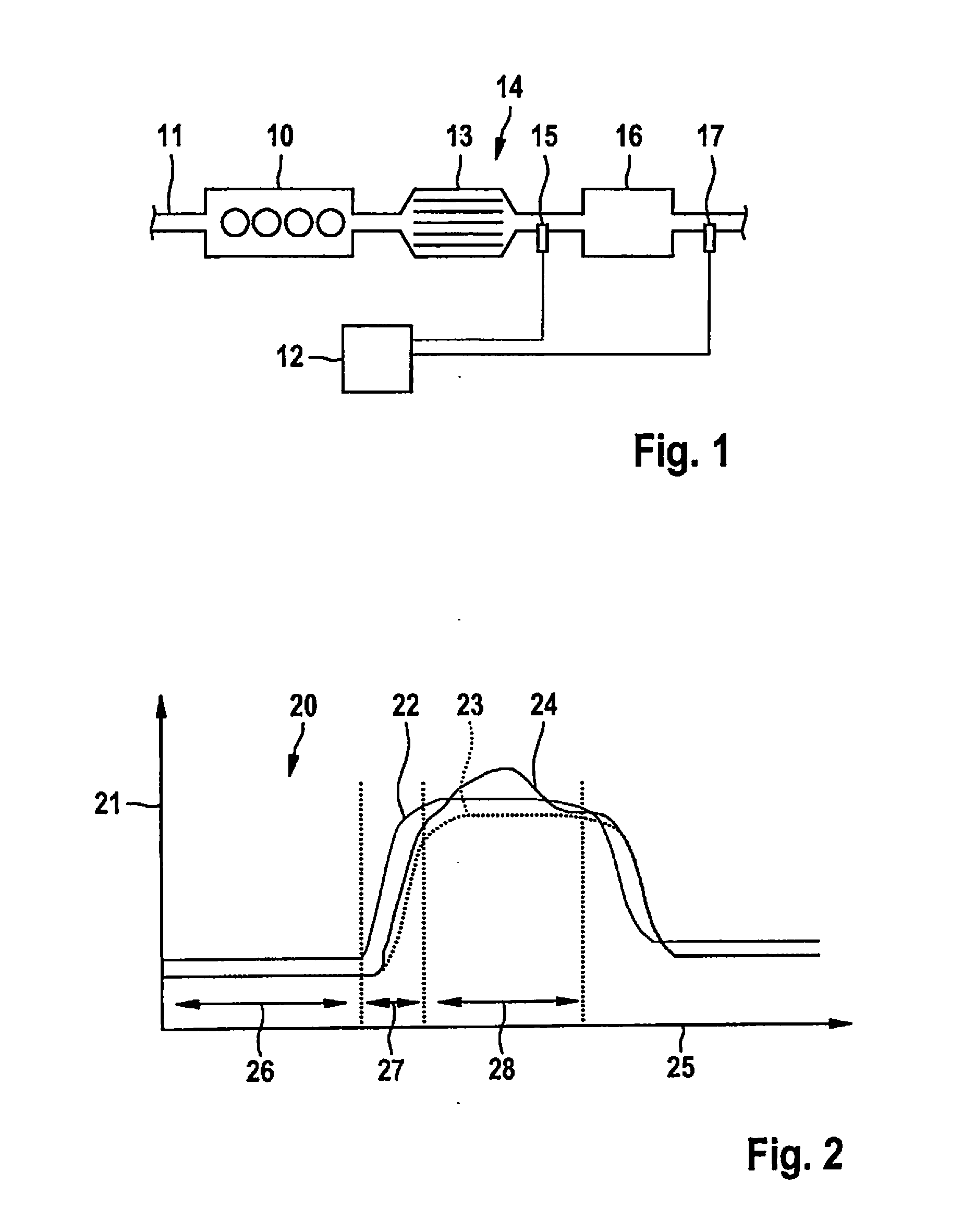
[0034]FIG. 1 shows the technical environment in which the present invention may be applied. An internal combustion engine 10 operated with gasoline is supplied with combustion air via an air supply 11 and emits exhaust gas via an exhaust duct 14. A three-way catalytic converter 13 is situated in exhaust duct 14 downstream from internal combustion engine 10, behind which in the direction of flow of the exhaust gas a particulate filter 16 is situated. The temperature of the exhaust gas is determined upstream of particulate filter 16 by a first temperature sensor 15 and downstream from particulate filter 16 by a second temperature sensor 17. First temperature sensor 15 and second temperature sensor 17 are connected to a control unit 12, in which their signals are analyzed in order to monitor on this basis a presence of particulate filter 16 and its functioning. In another specific embodiment, it is possible to determine the temperature of the exhaust gas upstream of particulate filter ...


PUM

PropertyMeasurementUnit
exhaust-gas temperatureaaaaaaaaaa
temperatureaaaaaaaaaa

Abstract

A method for monitoring a particulate filter in the exhaust duct of an internal combustion engine operated with gasoline, as a device for implementing the method are described. A first exhaust-gas temperature is determined upstream of the particulate filter and a second exhaust-gas temperature is determined downstream from the particulate filter, and a presence and / or a correct functioning of the particulate filter is inferred from a difference between the first and the second exhaust-gas temperature or from a differing time characteristic curve of the first and the second exhaust-gas temperature.

Description

BACKGROUND INFORMATION[0001]The present invention relates to a method for monitoring a particulate filter in the exhaust duct of an internal combustion engine operated with gasoline.[0002]The present invention furthermore relates to a device for monitoring a particulate filter in an exhaust duct of an internal combustion engine operated with gasoline, a control unit being assigned to the internal combustion engine.[0003]A particulate filter in the exhaust duct of gasoline-operated internal combustion engine is used to reduce the particulates emitted by the internal combustion engine. As in a particulate filter for an internal combustion engine operated with diesel fuel, it is also necessary in the case of an internal combustion engine operated with gasoline to regenerate the particulate filter when needed by burning off the particulates. This regeneration must be monitored. Furthermore, regulations provide for the correct functioning and the presence of the particulate filter to be ...

Claims


Application Information

Patent Timeline
Patent Type & Authority Applications(United States)
IPC IPC(8): F01N11/00G01K13/02G01M15/10
CPCF01N11/005G01M15/102F01N2560/06F01N2550/04G01K13/02F01N2900/1404Y02T10/40
Inventor WILLIMOWSKI, MARKUSBAARS, ENNOHANDLER, TORSTENWINKLER, KLAUSZEIN, THOMAS
Owner ROBERT BOSCH GMBH
Why Eureka
Try Eureka