
Suspension controlling apparatus for vehicle

a technology for controlling apparatus and suspension, which is applied in the direction of vehicle components, suspensions that are resilient, transportation and packaging, etc., can solve the problems that the appropriate control cannot sometimes be carried out for the behavior of the vehicle body, and the vibration of the brake hydraulic pressure is generated, so as to achieve the control of the suspension force and the effect of high responsibility and high degree of accuracy

Active Publication Date: 2016-09-22
HONDA MOTOR CO LTD
View PDF3 Cites 12 Cited by
  • Summary
  • Abstract
  • Description
  • Claims
  • Application Information

AI Technical Summary

Benefits of technology

This patent describes a system for controlling the suspension damping force of a vehicle. The system uses a map that determines the appropriate damping force based on acceleration and a derived value of acceleration. This allows for precise control of the suspension damping force during braking and acceleration. Additionally, the system takes into account the engine torque and gear ratio, resulting in even more precise calculations. This system also helps to prevent excessive variations in the damping force of the suspension.

Problems solved by technology

However, during antilock braking control, vibration of the brake hydraulic pressure is generated because braking and non-braking are repeated.
If the brake hydraulic pressure which vibrates in this manner is used in a suspension control, then appropriate control cannot sometimes be carried out for a behavior of the vehicle body.

Method used


Image

  • Suspension controlling apparatus for vehicle
  • Suspension controlling apparatus for vehicle
  • Suspension controlling apparatus for vehicle

Examples


Embodiment Construction

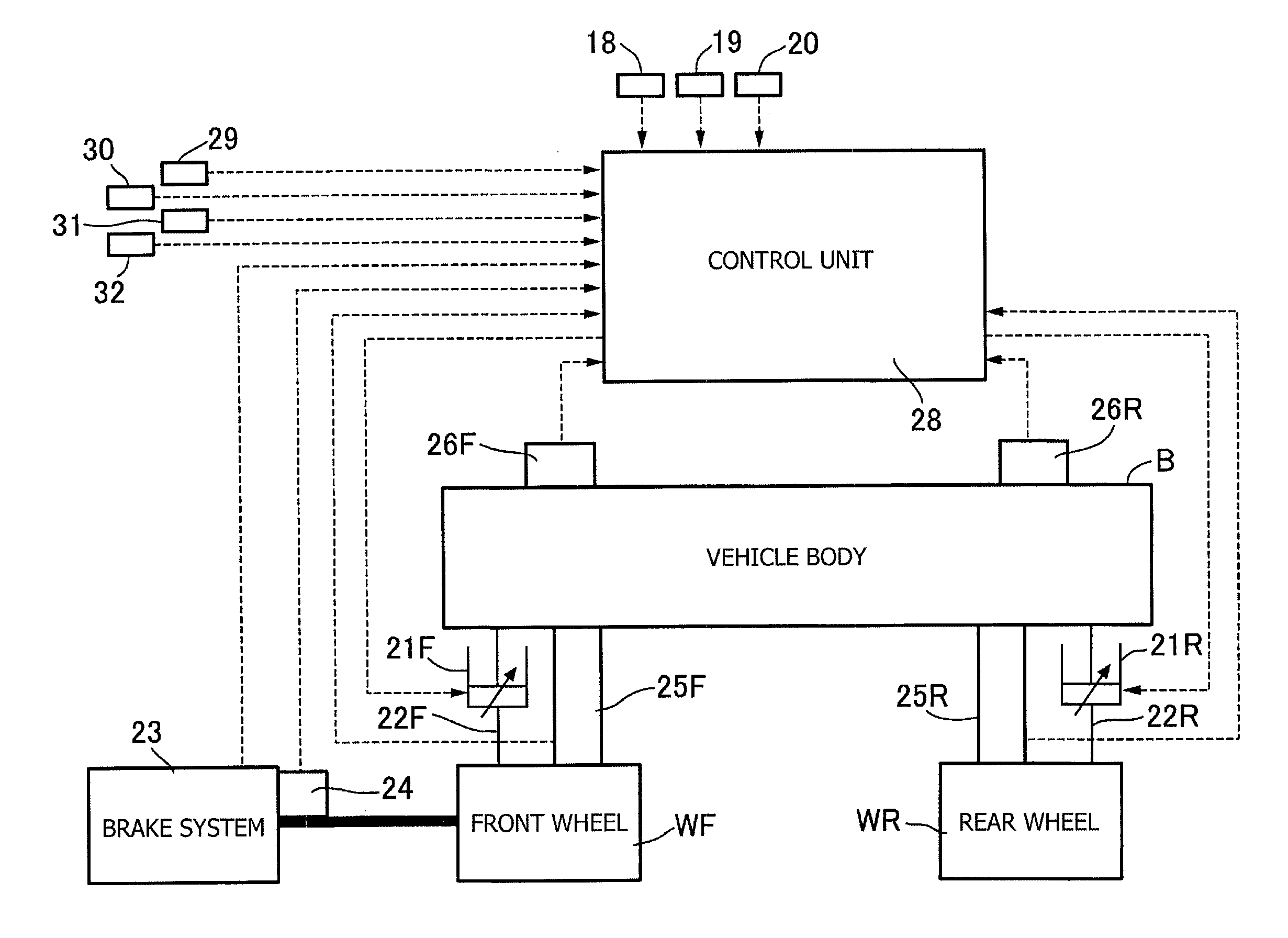
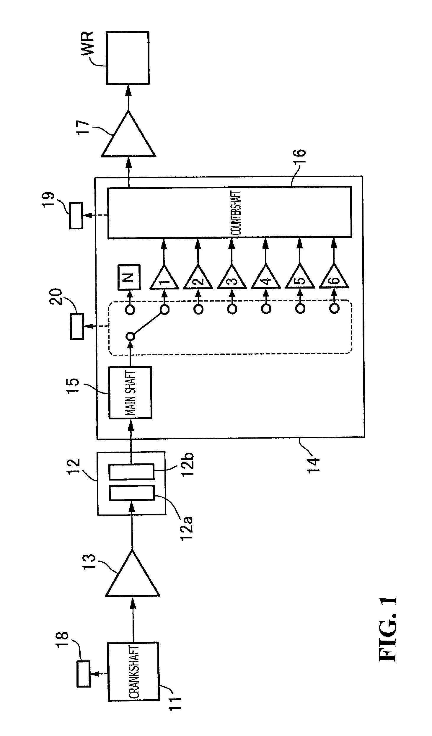
[0033]In the following, an embodiment of the present invention is described with reference to FIGS. 1 to 9. Referring first to FIG. 1, rotational power of a crankshaft 11 provided on an engine mounted on a vehicle such as a motorcycle is transmitted to an input member 12a of a clutch 12 through a primary reduction gear mechanism 13. The power from an output member 12b of the clutch 12 is inputted to a transmission 14. The transmission 14 is configured from selectively engageable first to sixth speed gear trains provided, for example, between a main shaft 15 and a countershaft 16. In a neutral state of the transmission 14, the rotational power transmitted from the output member 12b of the clutch 12 to the main shaft 15 is not transmitted to the countershaft 16. However, when the transmission 14 is not in the neutral state, the rotational power is transmitted to the countershaft 16 at a gear ratio given by selective engagement of the first to sixth speed gear trains. The rotational po...


PUM


Abstract

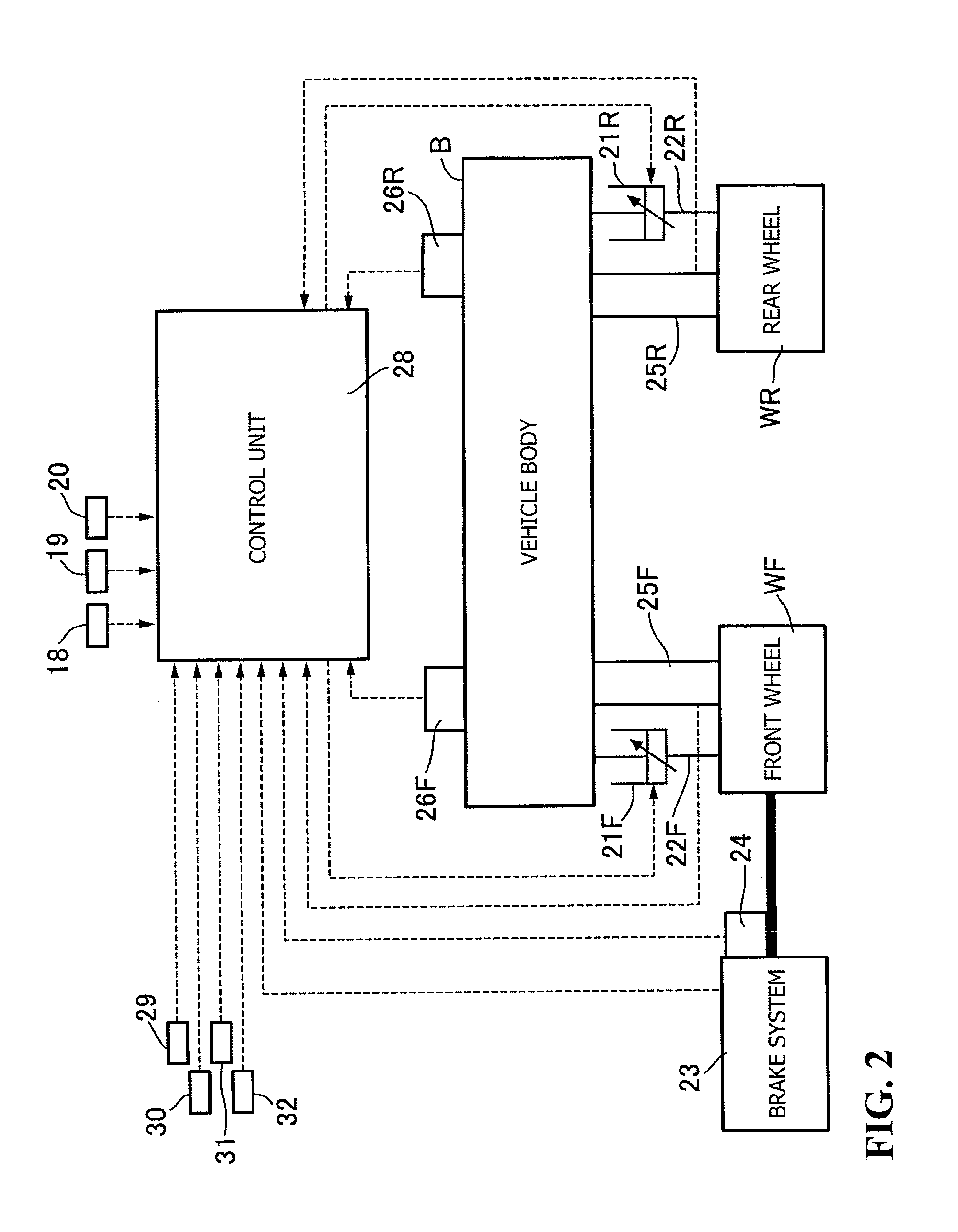
In a suspension controlling apparatus for a vehicle which includes a suspension whose damping force is variably settable and a control unit for calculating acceleration of the vehicle in a forward and rearward direction on the basis of brake hydraulic pressure detected by a hydraulic pressure sensor for detecting brake hydraulic pressure and is capable of controlling the damping force of the suspension with target damping force determined on the basis of the acceleration. In addition, appropriate control is also possible upon antilock braking control. A control unit includes an acceleration calculation device for calculating, upon ordinary braking, acceleration on the basis of ordinary braking force corresponding to a detection value of a hydraulic pressure sensor but calculating, upon antilock braking control, the acceleration on the basis of given antilock brake controlling braking force.

Description

CROSS-REFERENCE TO RELATED APPLICATIONS[0001]The present application claims priority under 35 USC 119 to Japanese Patent Application No. 2015-055853 filed Mar. 19, 2015 the entire contents of which are hereby incorporated by reference.BACKGROUND OF THE INVENTION[0002]1. Field of the Invention[0003]The present invention relates to a suspension controlling apparatus for a vehicle which includes a suspension whose damping force is variably settable, and a control unit for calculating the acceleration of the vehicle in a forward and rearward direction on the basis of brake hydraulic pressure detected by a hydraulic pressure sensor for detecting brake hydraulic pressure. The present invention is capable of controlling the damping force of the suspension with a target damping force determined on the basis of the acceleration.[0004]2. Description of Background Art[0005]A suspension controlling apparatus for a vehicle is known which carries out vibration suppression control of a suspension ...

Claims


Application Information

Patent Timeline
Patent Type & Authority Applications(United States)
IPC IPC(8): B60G17/016B60G17/019B60G17/06
CPCB60G17/0164B60G17/01908B60G17/019B60G17/06B60G17/016B60G17/08B60G2400/0511B60G2400/102B60G2400/204B60G2400/25B60G2400/252B60G2400/302B60G2400/33B60G2400/38B60G2400/39B60G2400/51B60G2500/10
Inventor NEDACHI, YOSHIAKI
Owner HONDA MOTOR CO LTD
Learn More