Power supply apparatus and control circuit therefor

a power supply apparatus and control circuit technology, applied in the direction of automatic control, process and machine control, instruments, etc., can solve the problems of output voltage being more likely to oscillate, output response and control system stability are contradictory, etc., to achieve excellent system stability and favorable response

Inactive Publication Date: 2006-07-18
TDK CORPARATION
View PDF16 Cites 12 Cited by
  • Summary
  • Abstract
  • Description
  • Claims
  • Application Information

AI Technical Summary

Benefits of technology

[0016]Such a power supply apparatus comprises the control circuit and a plurality of the power converter circuits connected in parallel and controlled by

Problems solved by technology

In a control system of a switching power supply, however, the output response and the stability of the control system are contradictory to ea

Method used


Image

  • Power supply apparatus and control circuit therefor
  • Power supply apparatus and control circuit therefor
  • Power supply apparatus and control circuit therefor

Examples


Embodiment Construction

[0023]In the following, the control apparatus for switching power supply apparatus and the switching power supply apparatus in accordance with embodiments will be explained with reference to the drawings.

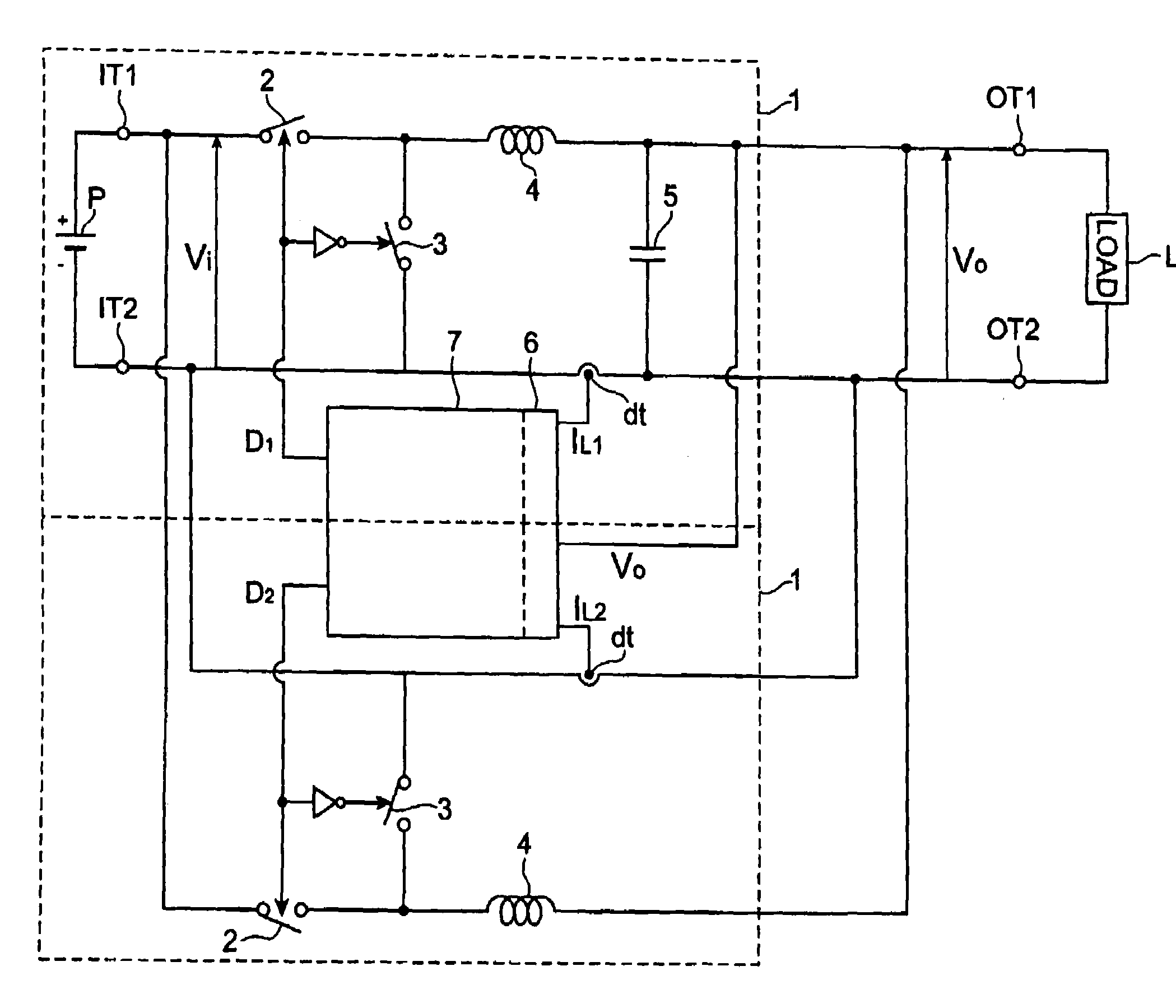
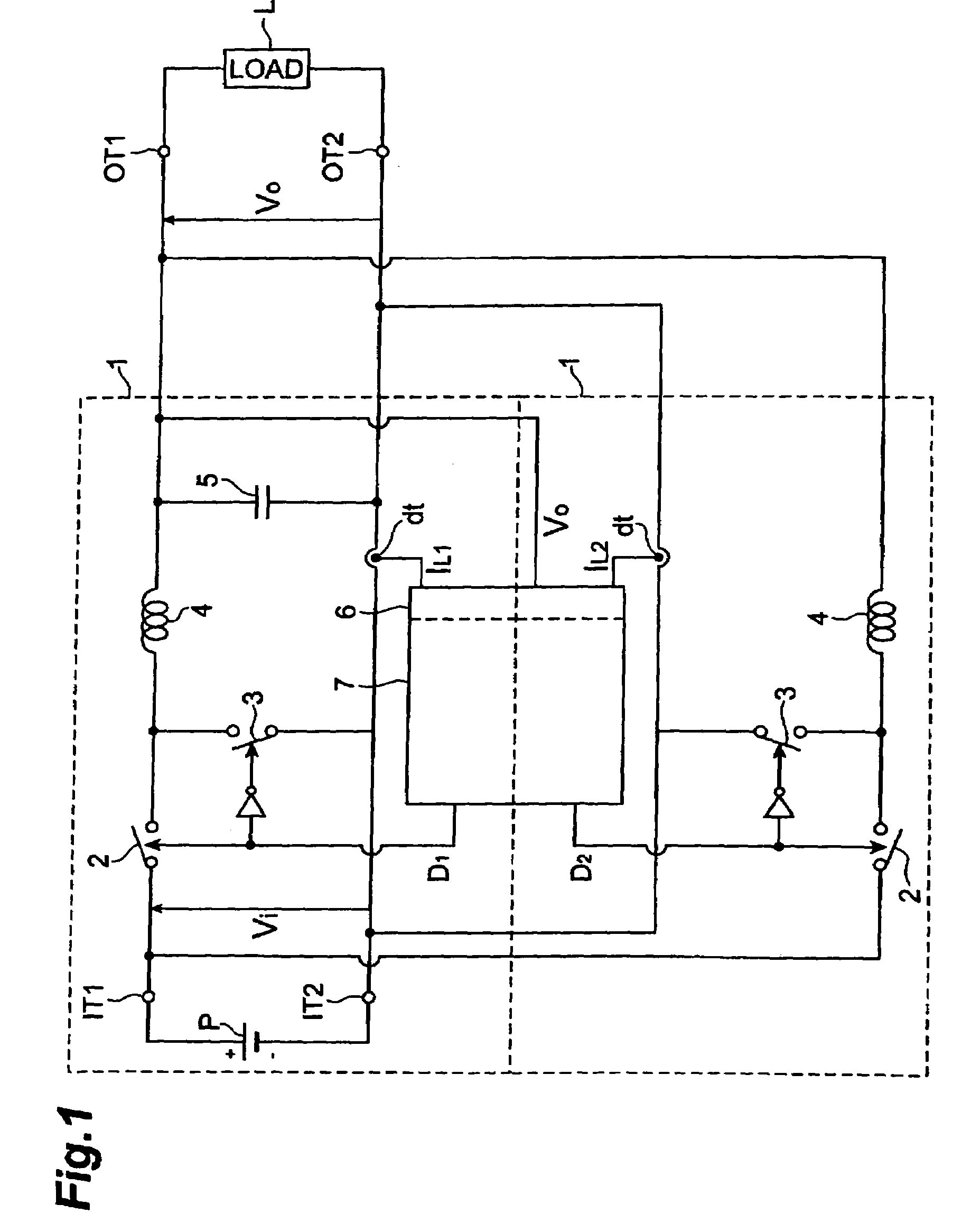
[0024]FIG. 1 is a block diagram of a power supply apparatus comprising a plurality of switching power supplies 1 arranged in parallel.

[0025]Each switching power supply 1 includes a pair of input terminals IT1, IT2 to which a DC voltage Vi is applied, and a pair of output terminals OT1, OT2 which are connected to a load L. One of the two input terminals IT1, IT2 is grounded, whereas the other is connected to one of potentials of a DC voltage source P. The load L is connected between the two output terminals OT1, OT2. These input and output terminals constitute a four-terminal circuit.

[0026]The load L is a destination to which an output voltage Vo output from the switching power supply 1 is fed. Examples of the load L include CPU (Central Processing Unit) and MPU (Micro Processing Uni...


PUM


Abstract

A selector sets respective phases of pulse driving signals in reverse when a proportion signal or integration signal does not exceed a threshold. Shifting the respective phases of the pulse driving signals from each other lowers the ripple voltage. When the load current increases drastically, the output voltage Vo tends to decrease remarkably because of the shortage of capacity in the power supply. In this case, when the proportion signal or integration signal exceeds its corresponding threshold, a phase control unit causes the pulse driving signals to synchronize their phases, i.e., the selector supplies the same ramp wave to the comparators, so that respective output voltages supplied from the DC voltage converter circuits attain the same phase, thereby restraining the output voltage supplied to the load from decreasing remarkably.

Description

BACKGROUND OF THE INVENTION[0001]1. Field of the Invention[0002]The present invention relates to a power supply apparatus comprising a plurality of power converter circuits connected in parallel, and a control circuit therefor.[0003]2. Related Background Art[0004]As a conventional switching power supply apparatus, one disclosed in Japanese Patent Application Laid-Open No. HEI 7-203672 has been known, for example. In a power supply apparatus employing a PWM control scheme which carries out voltage control for causing an actual output voltage value to coincide with a target voltage value, the switching power supply apparatus disclosed in the reference uses different output voltage controlling parameters for a start up period to the target voltage value and for a steady state after the target voltage value is attained, thereby providing a power supply apparatus which is excellent in start up period and steady-state characteristics.[0005]As the processing in microprocessors and digital ...

Claims


Application Information

Patent Timeline
IPC IPC(8): G05F1/59H02M3/158H02M3/155
CPCH02M3/1584Y02B70/1466H02M3/1588Y02B70/10
Inventor MIURA, KOICHIROUEMATSU, TAKESHIKAWASAKI, HIROSHIIMAI, TAKAKAZUMATSUURA, KEN
Owner TDK CORPARATION
Why Eureka
Try Eureka