Optical fiber reinforcement processing apparatus and optical fiber reinforcement processing method

a processing apparatus and optical fiber technology, applied in the field of optical fiber reinforcement processing apparatus, can solve the problems of hardly improving the working efficiency of the total fusion-splicing process, and achieve the effects of reducing the number of components, facilitating calibration of detected temperature, and improving temperature control

Active Publication Date: 2010-04-20
SUMITOMO ELECTRIC IND LTD
View PDF13 Cites 12 Cited by
  • Summary
  • Abstract
  • Description
  • Claims
  • Application Information

AI Technical Summary

Benefits of technology

[0018]According to the present invention, the heater itself which heats the reinforcing sleeve is used as a temperature detecting device. Therefore, a temperature detecting device such as a thermistor is not necessary, and the number of components can be reduced. Since the heater itself is used as a temperature detecting device, an accurate heating control in which the detected temperature is less varied by the attaching state and the degraded state can be performed, and calibration of the detected temperature can be facilitated. Moreover, the responsibility of the temperature control is improved, so that waste power consumption can be prevented from occurring.
[0019]Because of the temperature detection in which variation is reduced, and the accurate heating control, a process of heating the reinforcing sleeve from the middle portion toward the end portions can be stably performed. Furthermore, the heating process by the preliminary heating enables the heating time period in the main heating to be effectively shortened.

Problems solved by technology

Even when the fusion-splicing work is rapidly performed, therefore, the subsequent heating process work requires a prolonged time period, and hence the working efficiency of the total fusion-splicing process is hardly improved.

Method used


Image

  • Optical fiber reinforcement processing apparatus and optical fiber reinforcement processing method
  • Optical fiber reinforcement processing apparatus and optical fiber reinforcement processing method
  • Optical fiber reinforcement processing apparatus and optical fiber reinforcement processing method

Examples


Embodiment Construction

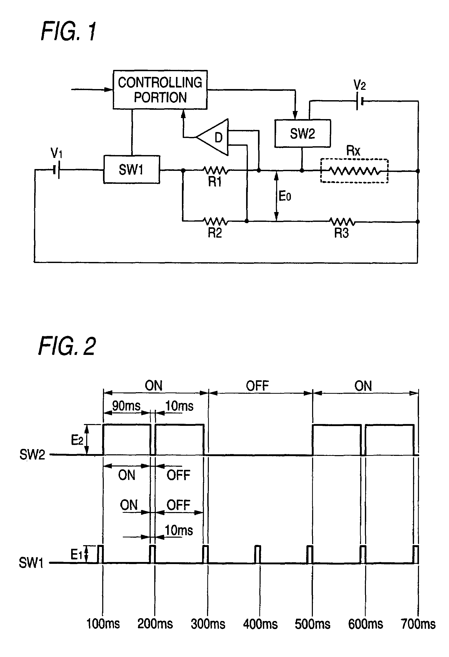
[0042]An embodiment of the invention will be described with reference to the figures. FIG. 1 is a circuit diagram schematically illustrating a heating control of the reinforcement processing apparatus of the present invention, and FIG. 2 is a view illustrating a state of power supply to a heater in the present invention.

[0043]A resistor Rx of the heater which is a heating member of the reinforcement processing apparatus of the present invention is connected in series to a first fixed resistor R1, and is incorporated as one resistance element of a bridge circuit in which the series circuit of the first fixed resistor R1 and the resistor Rx is connected in parallel to a series circuit of a second fixed resistor R2 and a third fixed resistor R3. A whole control circuit has first switching means SW1 which controls on / off operations of a first power source V1 in accordance with a control signal from a controlling portion, and second switching means SW2 which controls on / off operations of...


PUM


Abstract

An optical fiber reinforcement processing apparatus and reinforcement processing method are provided where it is not necessary to dispose a temperature detecting device such as a thermistor, and a heating control in which the detected temperature is not varied, the power consumption is low, and which is accurate is enabled.An optical fiber reinforcement processing apparatus in which a fusion-spliced portion of an optical fiber is covered by a heat-shrinkable reinforcing sleeve to perform reinforcement has: heating controlling means for performing a heating control on a heater which heats the reinforcing sleeve; and temperature detecting means for detecting a heating temperature of the heater on the basis of a change of the resistance of the heater. The heating control and the temperature detection are performed by controlling time periods of turning on / off a power supply to the heater. The temperature detection is performed by detecting a voltage change Eo of the midpoint of a bridge circuit in which a series circuit of a first fixed resistor R1 and a heater resistor RX, and a series circuit of a second fixed resistor R2 and a third fixed resistor R3 are connected in parallel.

Description

RELATED APPLICATIONS[0001]This application is the U.S. National Phase under 35 U.S.C. §371 of International Application No. PCT / JP2007 / 60068, filed on May 16, 2007, which in turn claims the benefit of Japanese Application No. 2006-137912, the disclosures of which Applications are incorporated by reference herein.TECHNICAL FIELD[0002]The present invention relates to an optical fiber reinforcement processing apparatus in which optical fibers are fusion-spliced to each other by a fusion-splicing apparatus, and thereafter a fusion-spliced portion is reinforced by a reinforcing sleeve, and also to a reinforcement processing method.BACKGROUND ART[0003]Optical fibers are fusion-spliced to each other by a fusion-splicing apparatus by removing fiber coatings of end portions to be fusion-spliced of the optical fibers, butting end portions of bare glass fibers which are exposed against each other, and heating and fusing the butted end portions to fusion-splice the end portions together. The ba...

Claims


Application Information

Patent Timeline
Patent Type & Authority Patents(United States)
IPC IPC(8): G02B6/255
CPCG02B6/2558G02B6/2551
Inventor MIYAMORI, MAKOTOHATTORI, KAZUNARI
Owner SUMITOMO ELECTRIC IND LTD
Why Eureka
Try Eureka