Reconfigurable Payload Systems (RPS) For Aircraft And Methods Related Thereto

a payload system and reconfigurable technology, applied in the field of aircraft, can solve the problems of increasing the cost of payload modification, extending the time schedule, and complicated design methods, and achieve the effect of saving time and expens

Active Publication Date: 2016-09-22
L3HARRIS TECH INTEGRATED SYST LP
View PDF12 Cites 11 Cited by
  • Summary
  • Abstract
  • Description
  • Claims
  • Application Information

AI Technical Summary

Benefits of technology

[0009]Disclosed herein are reconfigurable payload systems (RPS) and methods of configuring and using the same that may be employed in one embodiment to enable external aircraft payloads (e.g., such as environmental monitoring and intelligence gathering equipment, etc.) to be rapidly interchanged or swapped out together with associated internal equipment within a given aircraft so as to modify or change payload capability of the aircraft, e.g., to meet a particular mission and / or to enable use of future payload types for a fixed wing or rotary aircraft as they are developed. In such an embodiment, the disclosed systems and methods may be advantageously implemented on virtually any type of aircraft for a wide variety of applications external to the aircraft, allowing multiple different payload systems to be swapped in and out on a given aircraft as required based on needs for a given mission, saving time and expense over conventional single point design solutions. The disclosed reconfigurable payload systems and methods may be advantageously employed in one embodiment to rapidly configure and reconfigure aircraft mission technology based on changing per-mission requirements, allowing aircraft operators to share smaller quantities of sensor technology (i.e., sensors) and / or other types of payload devices since the payload devices may be distributed and changed (swapped) between RPS-equipped aircraft.
[0013]Advantageously, such an enveloped loads design method may be employed in conjunction with unique structural and / or electrical interface features of an RPS for a given aircraft or aircraft type to allow a multitude of payloads to be installed and / or interchanged on a given RPS-equipped aircraft with a substantial reduction in effort in analysis and design burden upon Stress, Mechanical Structures, and Electrical Aerospace Engineers. In this regard, a simplified verification of compliance with an established RPS loads envelope may be used to substantially reduce the effort required by Stress Aerospace Engineering to enable installation of new and / or different payloads. A relatively simple payload-to-rail or payload-to-hardpoint mounting RPS payload adapter design may also be provided to substantially reduce the design effort required by Mechanical Aerospace Engineering. A RPS quick-disconnect electrical interface device may be further provided to simplify design of specific payload electrical or other types of payload interface lines (e.g., hydraulic lines, liquid coolant lines for heat exchange cooling, etc.) associated with various payload / s, further reducing the required design effort by Mechanical and Electrical Aerospace Engineering. Moreover, in one exemplary embodiment, an RPS configured according to the enveloped design methodology and approved under an STC may be advantageously employed to allow multiple different payloads to be installed and / or interchanged on a given RPS-equipped aircraft without requiring a new or amended STC.
[0014]In one embodiment, a quick disconnect payload interface device (e.g., panel) may be employed to more easily modify the mechanical aspects of electrical interfaces when changing payloads, especially compared to the single-point solution method. In this regard, a RPS quick-disconnect payload interface device installed on an aircraft may be used to enable electrical and other types of payload interfaces associated with payloads to be relatively quickly and easily redefined for differing payloads. In one exemplary embodiment, a quick disconnect payload interface device may include a disconnect plug block that may be redefined to accommodate different harnesses without necessarily disturbing the aircraft structure and the body structure of the RPS quick-disconnect electrical interface device.
[0022]Thus, installation of a RPS may be common to a given aircraft or aircraft type such that the structure of a particular aircraft no longer requires a uniquely-designed aircraft structure modification's for compatibility with differing payload / s. For example, a given RPS may be designed in consideration of a desirable loads envelope resulting in a rail structure or fittings and mounting adapter that are configured to be installed on a given aircraft fuselage type such as a Beechcraft King Air 350. In similar manner, a RPS may be designed with a different loads envelope that is developed to address other aircraft types resulting in a different rail structure, or fittings and mounting adapter. In this regard, differing loads envelopes for other aircraft may be established and one or more components of an RPS subsequently designed, installed, and employed. Moreover, in one embodiment, once a given RPS design is created for installation on a given aircraft or aircraft type, corresponding installation tooling for RPS components may also be designed and manufactured to reduce cost and enhance ease of installation. This is possible since the given RPS design is common from aircraft-to-aircraft of the same type even though the working payloads may vary greatly. This in turn allows modification of the aircraft structure to become well known when implementing installation tooling which reduces touch labor and risk of damage during aircraft modification.

Problems solved by technology

The Beechcraft King Air 350, as well as many other types of fixed wing and rotary wing aircraft types are frequently modified using such single-point solutions that only meet a specific solution intent for a customer, thus driving increased costs and extended time schedules when payload modifications are required, e.g., due to new technology and differing payload capability requirements that are ever evolving.
Since the aircraft has already been modified with certain payload provisions, often is the case that the previously described design methodology will be complicated because of the impact of the currently installed aircraft modifications.
Some previously installed aircraft modifications may be difficult to remove or remove, modify, and reinstall without placing the aircraft structure at additional risk for damage during hands-on work.
In occurrence of such cases, the process can become unusually costly in expense and schedule.

Method used


Image

  • Reconfigurable Payload Systems (RPS) For Aircraft And Methods Related Thereto
  • Reconfigurable Payload Systems (RPS) For Aircraft And Methods Related Thereto
  • Reconfigurable Payload Systems (RPS) For Aircraft And Methods Related Thereto

Examples


Embodiment Construction

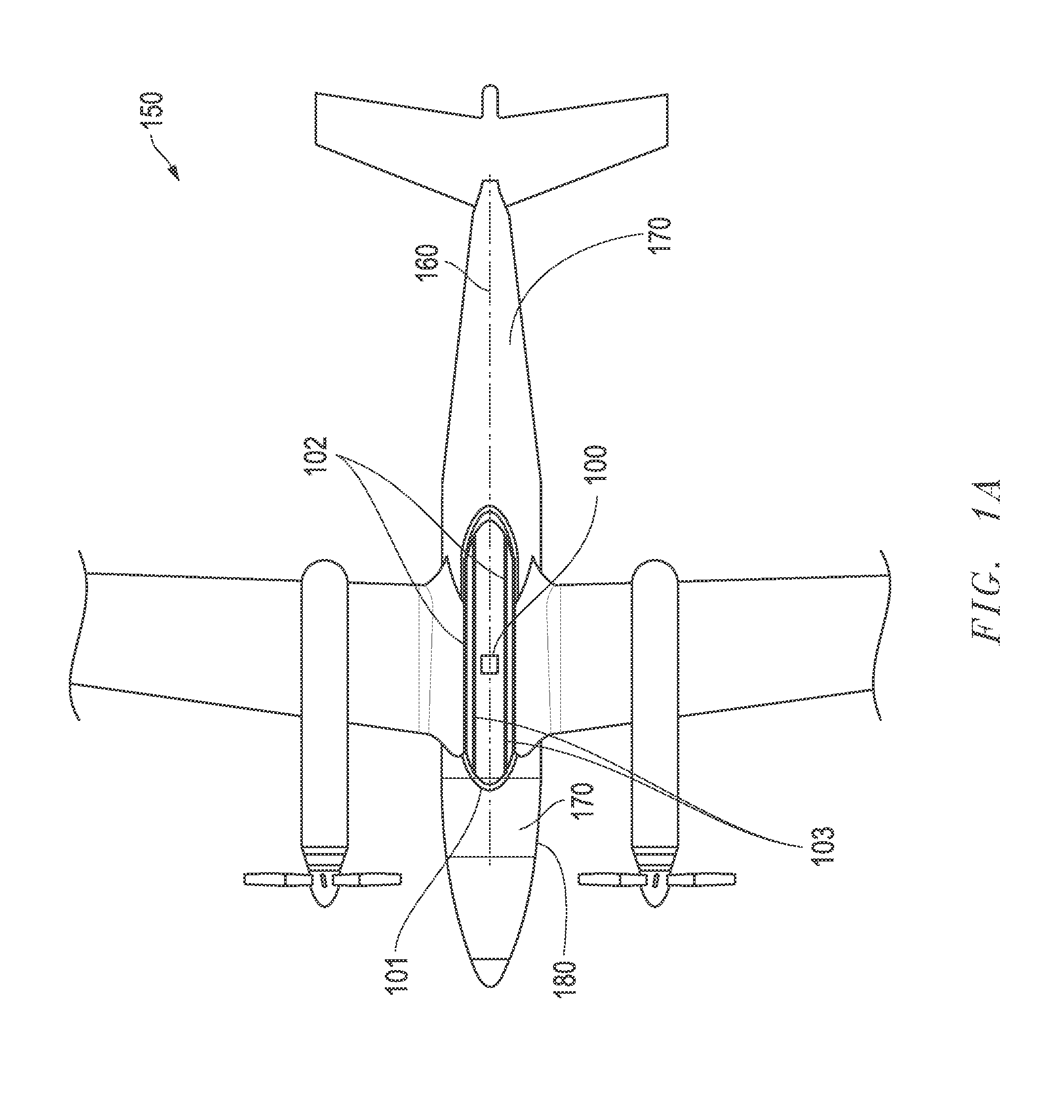
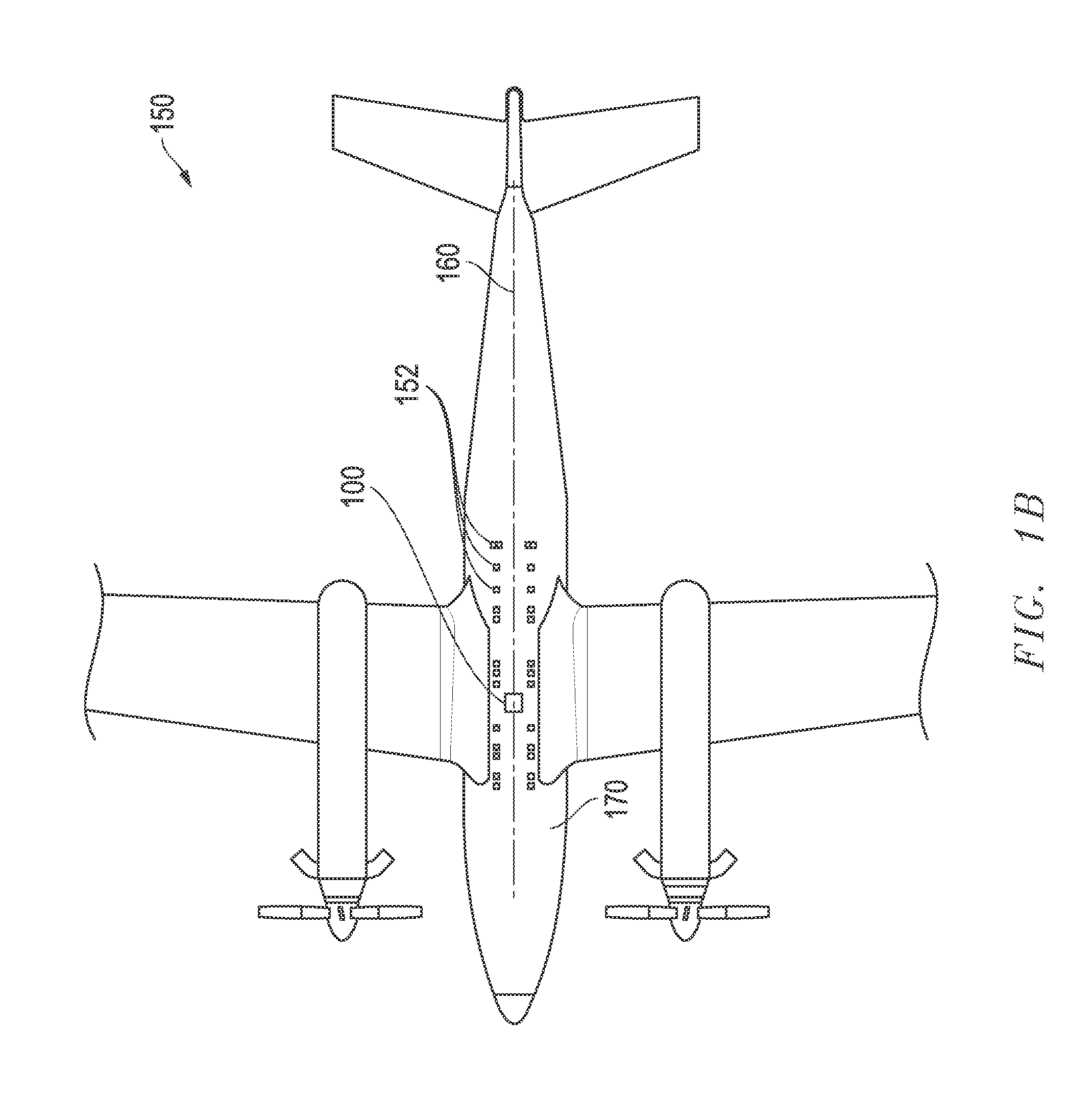
[0070]FIG. 1A illustrates a simplified bottom sectional view of a fixed winged aircraft 150 and installed components of a RPS according to one exemplary embodiment of the disclosed systems and methods. Although a fixed wing aircraft is illustrated, it will be understood that the disclosed systems and methods are equally applicable to rotary aircraft installations and configurations. In this particular embodiment, the installed components include a pair of substantially parallel inner payload rails 103 coupled to the structure of the aircraft 150, a pair of substantially parallel outer fairing rails 102 coupled to the structure of the aircraft 150, a quick disconnect panel 100, and an exemplary aerodynamic modular fairing 101 coupled to the outer fairing rails 102. In the illustrated embodiment, RPS is shown installed and oriented along and substantially parallel to the longitudinal axis 160 of aircraft 150 on the bottom side 170 of the aircraft fuselage 180. In one exemplary embodim...


PUM


Abstract

Reconfigurable payload systems (RPS) and methods of configuring and using the same are disclosed that may be employed to enable external aircraft payloads to be rapidly interchanged or swapped out together with associated internal equipment within a given aircraft so as to modify or change payload capability of the aircraft, e.g., to meet a particular mission and / or to enable use of future payload types as they are developed. The RPS and associated methods may be implemented to allow multiple different payload systems to be swapped in and out on a given aircraft as required based on needs for a given mission.

Description

[0001]This application claims the benefit of U.S. Provisional Patent Application Ser. No. 61 / 931,538, filed on Jan. 24, 2014 and entitled “Reconfigurable Payload Systems (RPS) For Aircraft and Methods Related Thereto”, which is incorporated herein by reference in its entirety for all purposes.[0002]The present application is related in subject matter to concurrently-filed PCT International Patent Application number ______ entitled “Reconfigurable Payload Systems (RPS) For Aircraft and Methods Related Thereto” by Hodge et al., and to concurrently-filed U.S. patent application Ser. No. ______ entitled “Reconfigurable Payload Systems (RPS) With Operational Load Envelopes For Aircraft and Methods Related Thereto” by Hodge et al., each of which is filed on the same date as the present application and which is incorporated herein by reference in its entirety for all purposes.FIELD OF THE INVENTION[0003]This application relates to aircraft and, more particularly, to reconfigurable payload ...

Claims


Application Information

Patent Timeline
Patent Type & Authority Applications(United States)
IPC IPC(8): B64D9/00
CPCB64C2211/00B64D9/00B64D7/00
Inventor HODGE, BEN D.TROUP, TIMOTHY W.CROPPER, RICHARD D.STOKES, BRANDY D.
Owner L3HARRIS TECH INTEGRATED SYST LP
Why Eureka
Try Eureka