
Combined cycle combustion engine process and combined cycle combustion engine

a combustion engine and combustion engine technology, applied in the field of combined cycle combustion engine process and combined cycle combustion engine, can solve the problems of volumetric efficiency loss, high cost, and high cost of combustion engine, and achieve the effect of reducing the cost of combustion engin

Inactive Publication Date: 2016-09-22
SAKAI MASSAO
View PDF2 Cites 0 Cited by
  • Summary
  • Abstract
  • Description
  • Claims
  • Application Information

AI Technical Summary

Benefits of technology

The invention is a combined cycle engine system that uses innovative techniques to improve thermal energy utilization and reduce emissions. The system includes a high pressure steam cycle, the injection of purged condensate in the low pressure drum to reduce temperature in power stroke, the use of ejector to improve exhaustion gas expelling, the use of condenser to recover water in the system, and the recovery of heat from the engine through the use of a heat recovery steam generator. The system also includes a pre-heater, a pre-cooling system, and a water incondensable part release system to control piston work yield and improve engine performance. The invention has been tested and shown to improve engine performance and reduce emissions.

Problems solved by technology

The reduction of combustion temperature is obtained with excess of combustion air (which causes efficiency losses) or with the recirculation of combustion gases (which causes volumetric efficiency losses).
This conception is only viable in large-scale facilities due to the need of a repository water treatment plant to comply with the turbine steam requirements.
This conpection has the disadvantage of require significative modifications in combustion engine project, with characteristics in valves and controls that differs of convention an engine, besides the collector system for discharge steam and its recovery to replace the process water.
The injection of low pressure steam increases the engine compression power, but it is not effective in temperature reduction compared with the injection of condensed steam proposed by this current patent application.

Method used


Image

  • Combined cycle combustion engine process and combined cycle combustion engine
  • Combined cycle combustion engine process and combined cycle combustion engine
  • Combined cycle combustion engine process and combined cycle combustion engine

Examples


Embodiment Construction

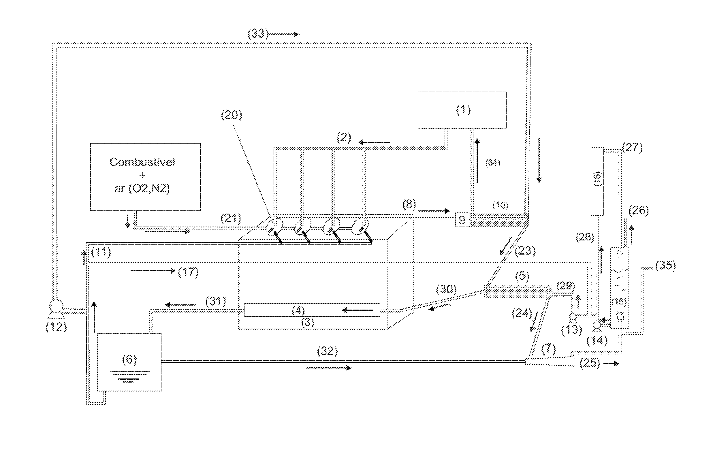
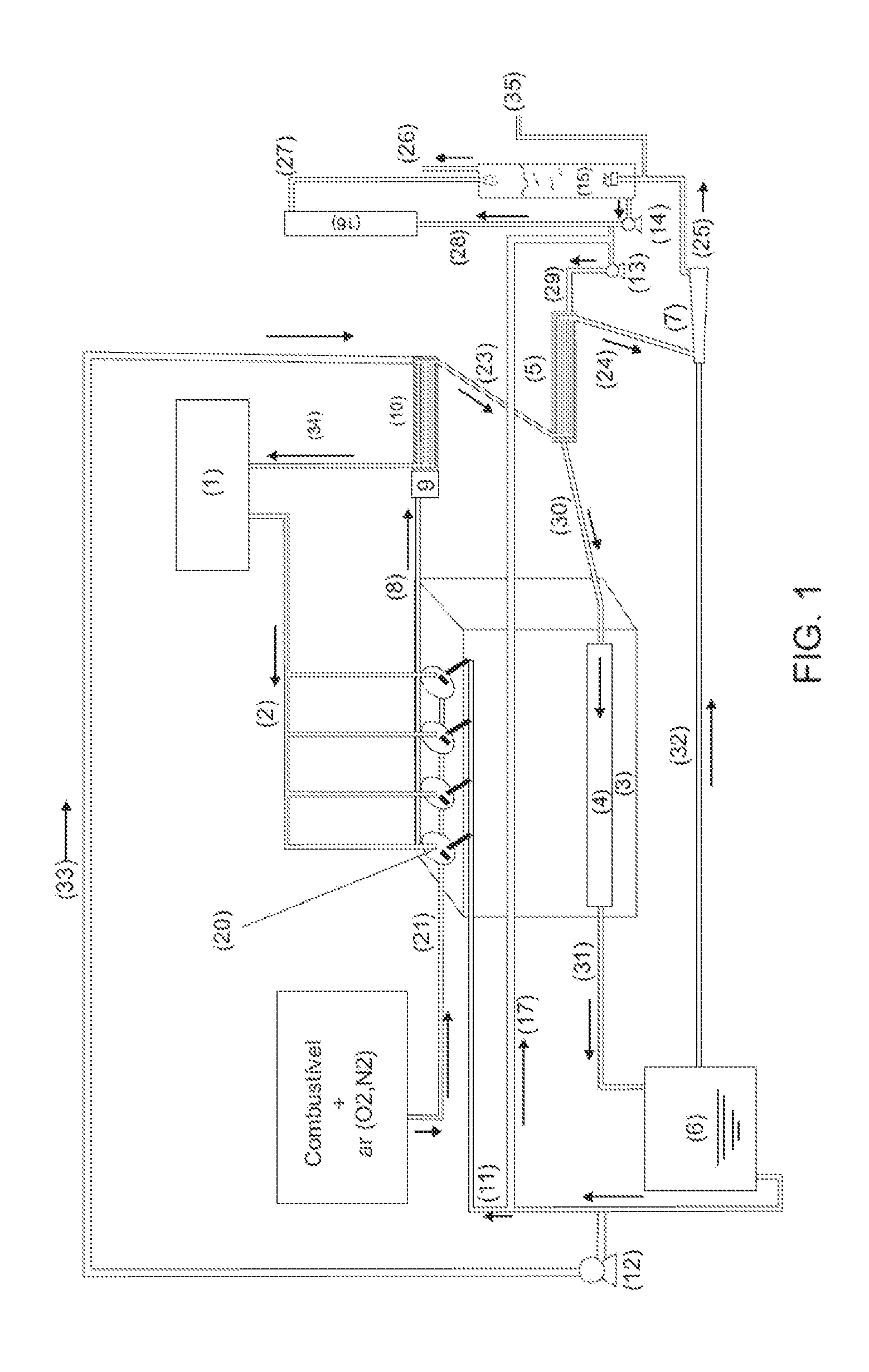
[0029]This invention is based on recovered thermal energy, that is rejected by a conventional internal combustion engine either by combustion gases exhaustion or by cooling system, using the combination of five technics that are innovative when compared with the state of art:

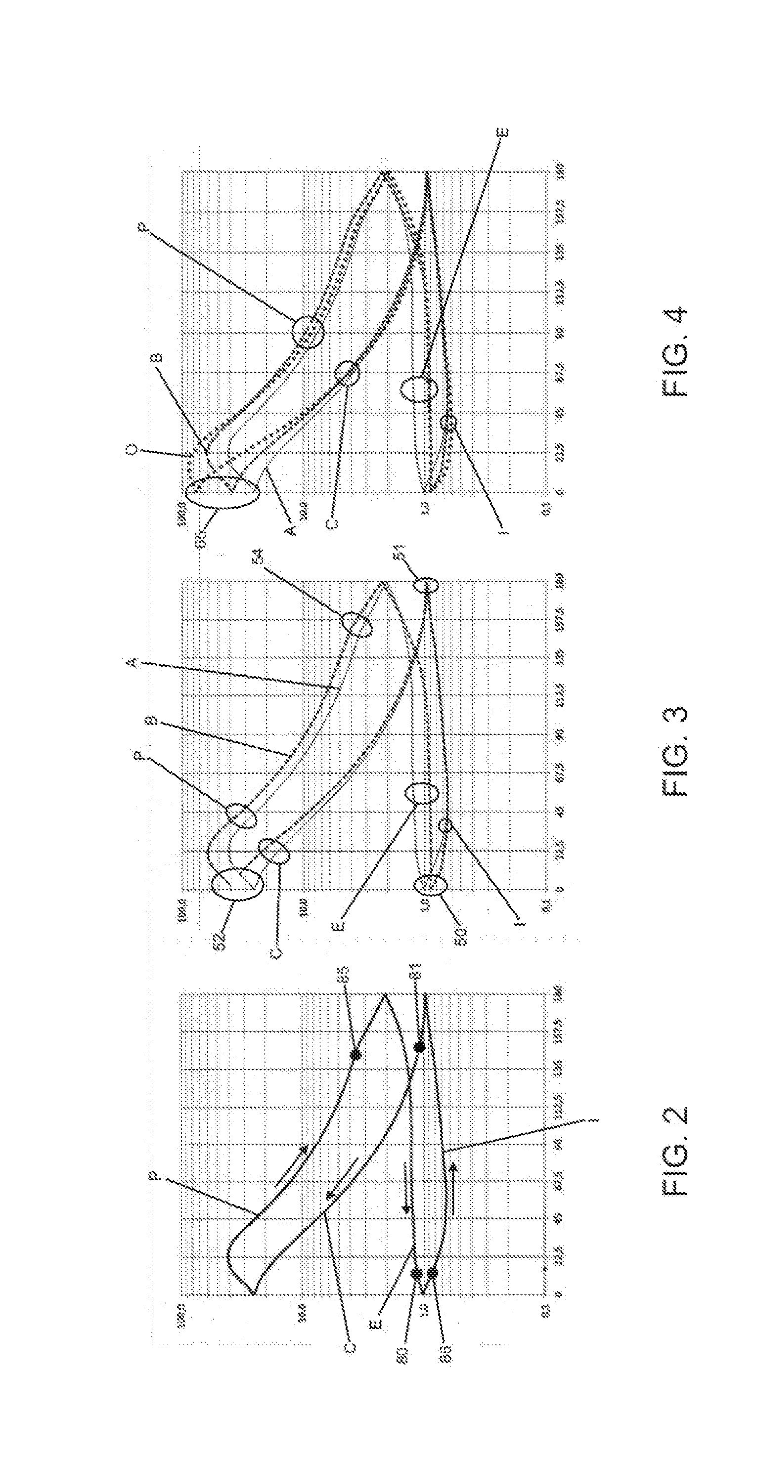
[0030]a) innovation 1: high pressure steam cycle, which steam is injected in the engine in order to reduce the temperature in power (P) stroke, but increases the internal pressure in the cylinders, increasing the piston work yield inside combustion chamber (20). The reduction of temperature reduces the NOx formation;

[0031]b) innovation 2: the injection of purged condensate from the low pressure drum (6) inside the combustion chamber (20) in the end of exhaustion (E) stroke. This injection allows a better expelling of combustion gas in the end of exhaustion (E) and controls the internal temperature of cylinders in compression (C), enabling a higher compression rate and higher piston work yield;

[0032]c) innovation...


PUM


Abstract

The invention describes an Otto cycle or Diesel cycle internal combustion engine assembled with an energy and water recovery systems to Rankine cycle. In the first innovation, the high pressure steam, preferably above critical pressure, is injected in combustion chamber (20) in the end of compression (C) stroke reducing the combustion temperature and increasing internal pressure in the cylinder.

Description

FIELD OF APPLICATION[0001]The present invention is related to an internal combustion engine, in which is applied the combined cycle concept used in thermoelectric power plant, combining the Otto or Diesel cycle with Rankine cycle, aiming the improvement of thermal yield e, consequently, the reduction of fuel consumption. Moreover, the invention allows to improve the quality of exhaustion gases released to the atmosphere reducing the concentration of Nox and particulated material.BACKGROUND[0002]Combustion engines work with the burning of fuel, that are explosive chemical substances. This explosion happens inside a combustion chamber (20) especially designed to transform the energy released by explosion in mechanical movement of piston.[0003]From 1980's, it has been used the concept of combined cycle in thermoelectric power plants and, according to it, the fossil fuel has been burned in gas turbine with around 30% efficiency, and the thermal loss around 70%, using in steam generation...

Claims


Application Information

Patent Timeline
Patent Type & Authority Applications(United States)
IPC IPC(8): F01K23/06F02B47/02F02G5/04
CPCF01K23/065F02B47/02F02G5/04Y02E20/16Y02T10/12
Inventor SAKAI, MASSAO
Owner SAKAI MASSAO
Learn More