
Magnetic bead-based digital microfluidic immunoanalysis device and method thereof

a digital microfluidic and immunoanalysis technology, applied in measurement devices, scientific instruments, instruments, etc., can solve the problems of reducing unable to prevent the situation of leaked magnetic beads, and fixing the magnetic beads, so as to reduce the probability of magnetic beads leaked

Active Publication Date: 2016-09-22
NAT CHIAO TUNG UNIV
View PDF1 Cites 9 Cited by
  • Summary
  • Abstract
  • Description
  • Claims
  • Application Information

AI Technical Summary

Benefits of technology

The invention is about a device and method for analyzing magnetic beads in a digital microfluidic system. By using multiple electrodes of different sizes, the device can attract the magnetic beads and direct them to a detection area, where they can be used in the analysis. This reduces the likelihood of the magnetic beads leaking out of the system, which could contaminate the sample or cause other issues. Overall, this technology allows for more accurate and reliable analysis using small amounts of magnetic beads.

Problems solved by technology

However, this technique is unable to fix the magnetic beads to persist in the droplet through a magnetic force, so that parts of the magnetic beads are removed along with the excess waste-liquid.
In this way, current magnetic bead-based digital microfluidic immunoanalysis chips use large amounts of magnetic beads in order to lower the percentage of leaked magnetic beads to lower the effect that leaked magnetic beads has, however the situation of leaked magnetic beads is still unable to be prevented.
In particular, low concentration conditions may cause the detection signal to be lower than the detection limits of the measuring apparatus and the detection signal may be unable to be measured.

Method used


Image

  • Magnetic bead-based digital microfluidic immunoanalysis device and method thereof
  • Magnetic bead-based digital microfluidic immunoanalysis device and method thereof
  • Magnetic bead-based digital microfluidic immunoanalysis device and method thereof

Examples


Embodiment Construction

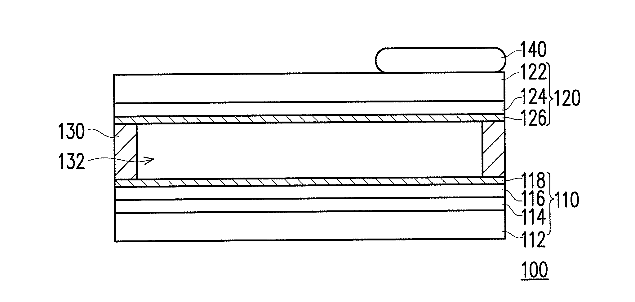
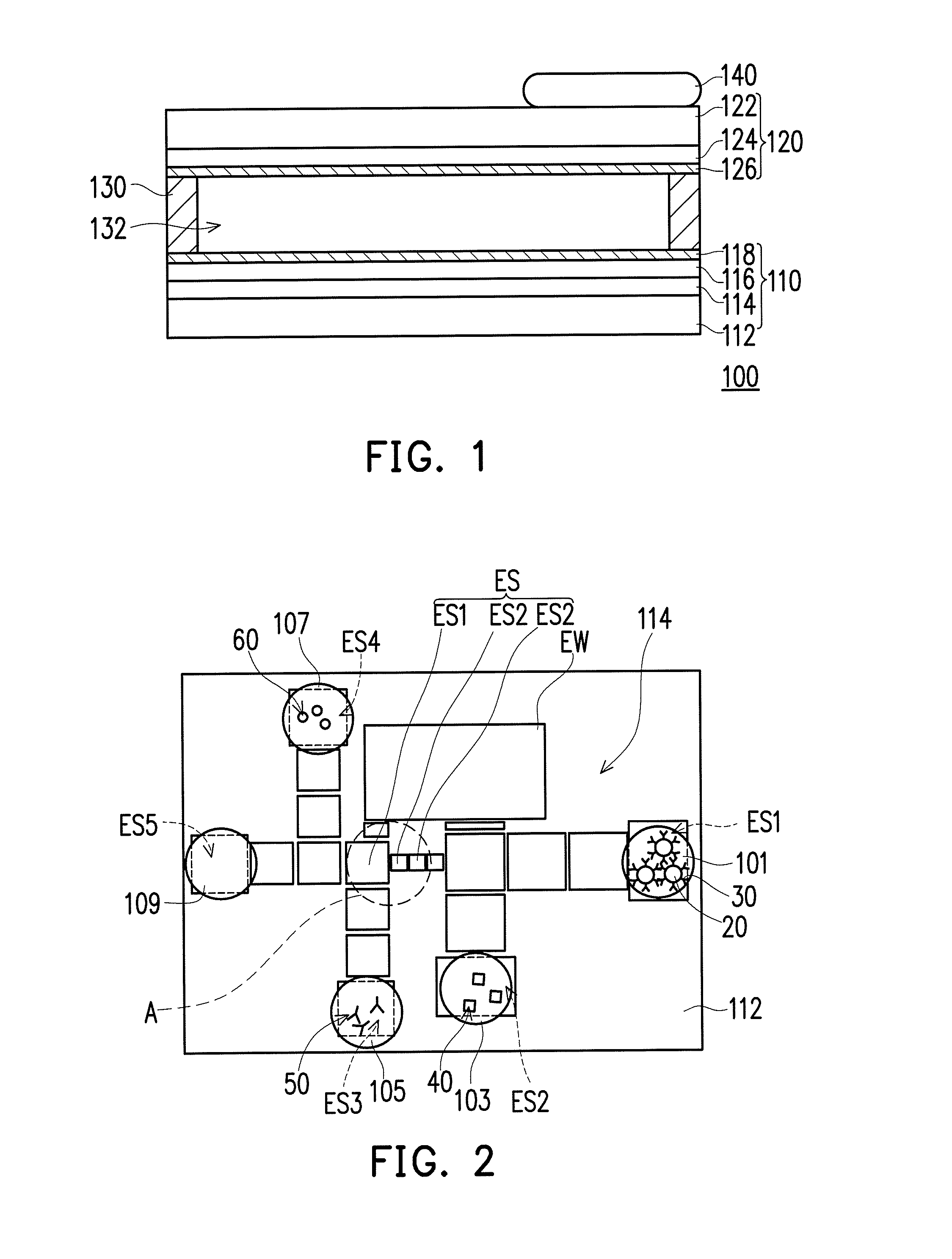
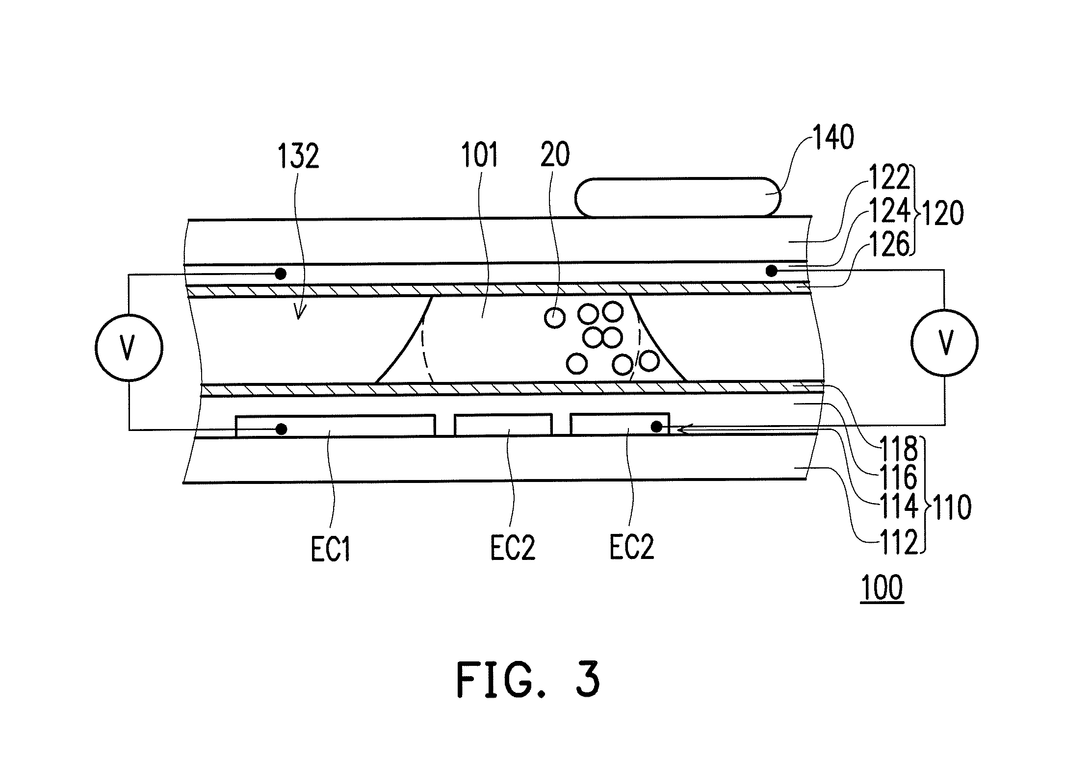
[0021]FIG. 1 is a schematic side view of a magnetic bead-based digital microfluidic immunoanalysis device according to an embodiment of the invention. Referring to FIG. 1, in the present embodiment, a magnetic bead-based digital microfluidic immunoanalysis device 100 is adapted for performing digital microfluidic immunoanalysis using a few magnetic beads 20 (shown in FIG. 2). Performing digital microfluidic immunoanalysis using a few magnetic beads 20 refers to a number of the magnetic beads 20 used for the present embodiment is fewer than 100, but in actuality the number may be adjusted according to requirements and should not be construed as a limitation to the invention. The magnetic bead-based digital microfluidic immunoanalysis device 100, for example, is a magnetic bead-based digital microfluidic immunoanalysis chip, which includes a lower plate 110, an upper plate 120, a separating structure 130 and a magnet 140. A droplet 101 containing magnetic beads 20 (shown in FIG. 2) is...


PUM

PropertyMeasurementUnit
timeaaaaaaaaaa
sizesaaaaaaaaaa
magnetic forceaaaaaaaaaa

Abstract

A magnetic bead-based digital microfluidic immunoanalysis device and a method thereof are provided, which includes a lower plate, an upper plate disposed above the lower plate, a separating structure therebetween and a magnet disposed on the upper plate or the lower plate. The lower plate includes a first electrode layer including a plurality of channel electrodes with different sizes. A droplet containing few magnetic beads is adapted to be disposed on the lower plate and corresponding to the channel electrodes. The magnet attracts the magnetic beads to approach to the smaller one of the channel electrodes though a magnetic force, and when a voltage is applied to the first electrode layer, the droplet is divided to a detection portion with the magnetic beads and a waste-liquid portion without the magnetic beads respectively corresponding to the smaller one and the larger one of the channel electrodes through a dual-direction electrowetting-on-dielectric force.

Description

CROSS-REFERENCE TO RELATED APPLICATION[0001]This application claims the priority benefit of Taiwan application serial no. 104108305, filed on Mar. 16, 2015. The entirety of the above-mentioned patent application is hereby incorporated by reference herein and made a part of this specification.BACKGROUND OF THE INVENTION[0002]1. Field of the Invention[0003]The present invention relates to a microfluidic immunoanalysis device and method thereof, and relates particularly to a magnetic bead-based digital microfluidic immunoanalysis device and method thereof.[0004]2. Description of Related Art[0005]In recent years, immunoassay has become one of the most commonly used detection methods in laboratories, and may be used for detecting the concentration of target objects in biological fluids. The principle of immunoassay is in fixing a capture antibody on a solid phase carrier and adding a target antigen as a target. At this time, the capture antibody on the solid phase carrier and the target ...

Claims


Application Information

Patent Timeline
Patent Type & Authority Applications(United States)
IPC IPC(8): G01N33/543G01N27/447
CPCG01N33/54333G01N27/44791G01N27/44704G01N27/745G01N33/573G01N33/6863
Inventor HSU, WENSYANGHUANG, CHENG-YEHTSAI, PO-YENSHIH, PO-HUAIFAN, SHIH-KANGYAO, DA-JENGLIU, CHENG-HSIENHUANG, HONG-YUAN
Owner NAT CHIAO TUNG UNIV
Learn More