Timing signal generation device and electronic apparatus

a technology of timing signal and electronic equipment, which is applied in the direction of measurement devices, instruments, satellite radio beaconing, etc., can solve the problem of not ensuring the accuracy of 1 pps, and achieve the effect of ensuring the temporal accuracy of a standard signal

Active Publication Date: 2016-09-22
MICROCHIP TECH INC
View PDF1 Cites 16 Cited by
  • Summary
  • Abstract
  • Description
  • Claims
  • Application Information

AI Technical Summary

Benefits of technology

[0013]An advantage of some aspects of the invention is to provide a timing signal generation device and an electronic apparatus capable of ensuring temporal accuracy of a standard signal.

Problems solved by technology

Therefore, there is the problem that accuracy of the 1 PPS may not be ensured.

Method used


Image

  • Timing signal generation device and electronic apparatus
  • Timing signal generation device and electronic apparatus
  • Timing signal generation device and electronic apparatus

Examples


first embodiment

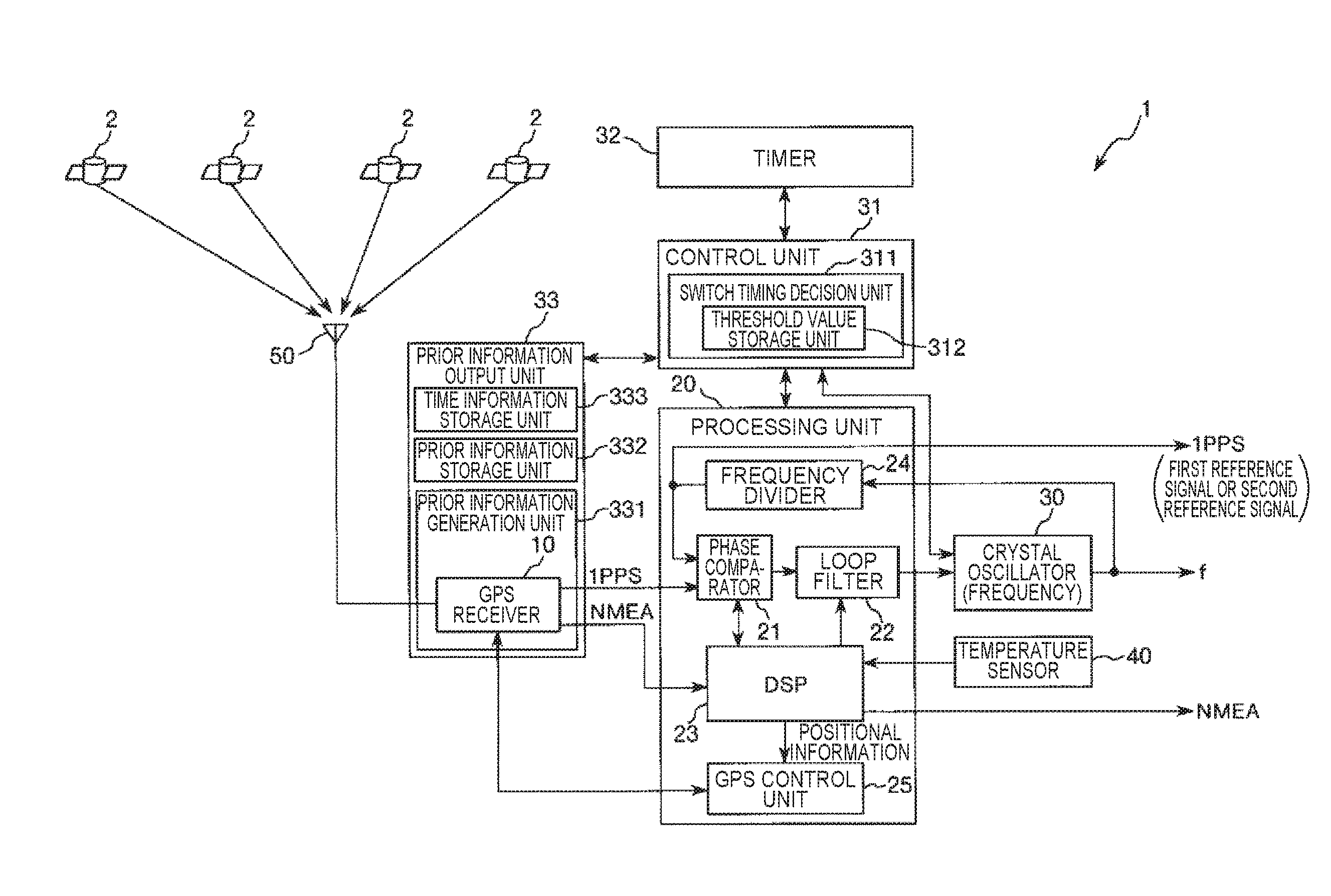
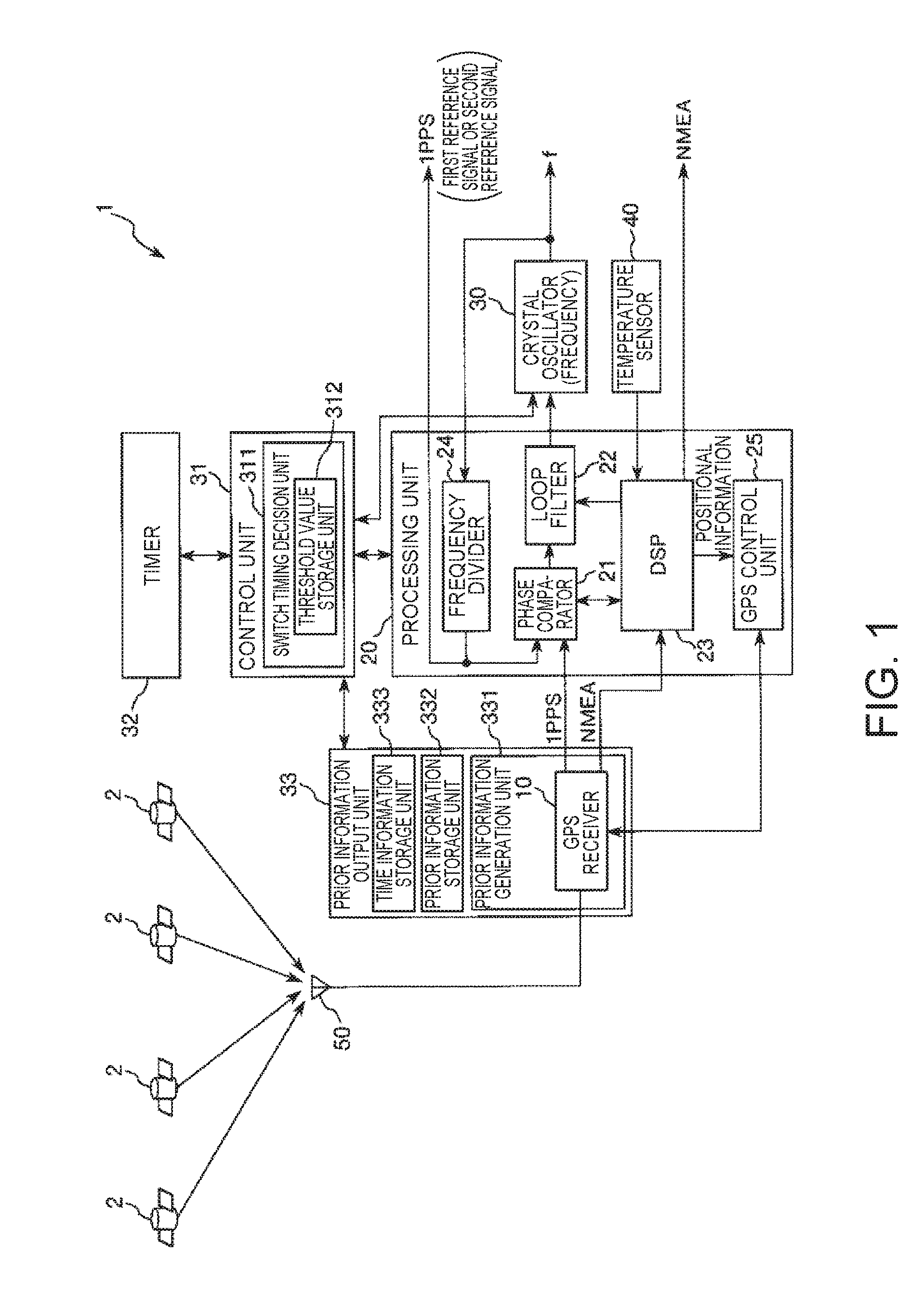
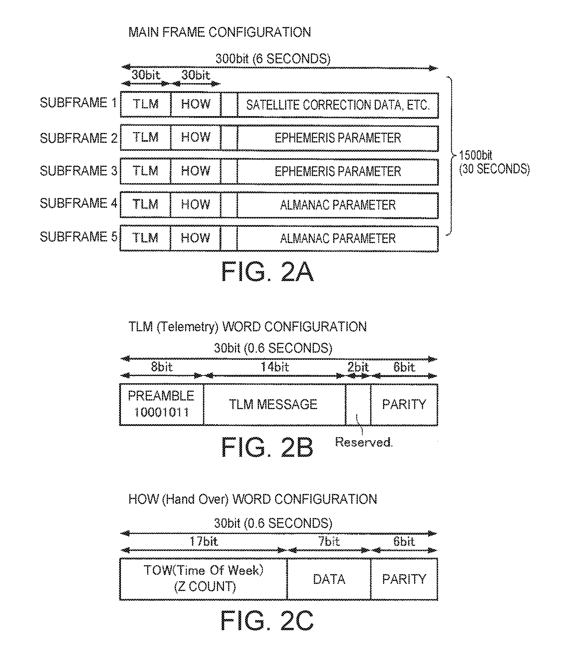
[0047]FIG. 1 is a diagram illustrating a schematic configuration of a first embodiment of a timing signal generation device according to the invention. FIGS. 2A to 2C are diagrams illustrating the configuration of a navigation message transmitted from a GPS satellite. FIG. 3 is a block diagram illustrating an example of the configuration of a GPS receiver included in the timing signal generation device illustrated in FIG. 1. FIG. 4 is a graph illustrating a relation between a time and an accuracy deterioration rate of a satellite signal in the timing signal generation device illustrated in FIG. 1. FIG. 5 is a graph illustrating a relation between a time and a control voltage obtained based on the satellite signal and input to a crystal oscillator in the timing signal generation device illustrated in FIG. 1.

[0048]A timing signal generation device 1 illustrated in FIG. 1 includes a GPS receiver (receiver) 10 serving as a satellite signal reception unit, a processing unit (CPU) 20 serv...

second embodiment

[0133]FIG. 6 is a diagram illustrating a schematic configuration of main units of a second embodiment of the timing signal generation device according to the invention. FIG. 7 is a graph illustrating a relation between a time and an accuracy deterioration rate of a satellite signal in the timing signal generation device illustrated in FIG. 6.

[0134]In the second embodiment, differences from the above-described first embodiment will be mainly described below and the description of the same matters will be omitted.

[0135]As illustrated in FIG. 6, in the timing signal generation device 1 according to the second embodiment, the GPS antenna 50 is installed in an outside surface 43 of a wall 42 of a building 41. The GPS antenna 50 is disposed at a position lower than the height of the building 41.

[0136]In this case, depending on a period of time (time), some of the radio waves sent from four GPS satellites 2 may be blocked by the building 41 in some cases. In the example illustrated in FIG....


PUM


Abstract

A timing signal generation device includes: an output terminal that outputs a standard signal; a first standard signal generation unit that generates a first standard signal based on a reference signal input from outside; a second standard signal generation unit that generates a second standard signal based on a signal output from an oscillator; and a control unit that switches the standard signal output from the output terminal from the first standard signal to the second standard signal based on prior information indicating that accuracy of the reference signal deteriorates.

Description

CROSS REFERENCE[0001]This application claims benefit of Japanese Application No. 2015-054045, filed on Mar. 17, 2015. The disclosure of the prior application is hereby incorporated by reference herein in its entirety.BACKGROUND[0002]1. Technical Field[0003]The present invention relates to a timing signal generation device and an electronic apparatus.[0004]2. Related Art[0005]The global positioning system (GPS) which is one of the global navigation satellite systems (GNSS) using artificial satellites is widely known. Atomic clocks with considerably high accuracy are mounted on GPS satellites used for the GPS. Satellite signals on which trajectory information of GPS satellites or accurate time information or the like is superimposed are transmitted to the ground. The satellite signals transmitted from the GPS satellites are received by GPS receivers. Then, the GPS receivers perform a process of calculating time information or the current positions of the GPS receivers based on the tra...

Claims


Application Information

Patent Timeline
Patent Type & Authority Applications(United States)
IPC IPC(8): G01S19/37
CPCG01S19/37G01S19/14
Inventor MAKI, YOSHIYUKISHIMADA, HIROYUKI
Owner MICROCHIP TECH INC
Why Eureka
Try Eureka