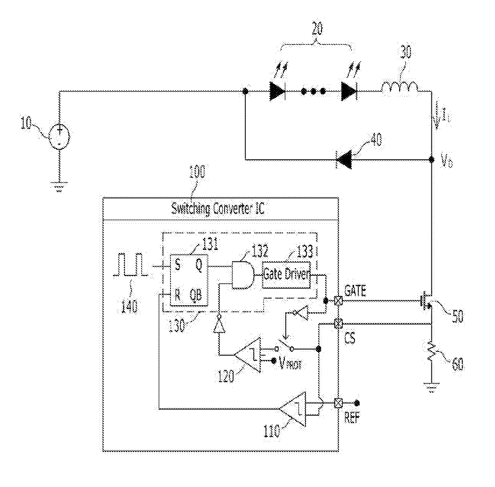
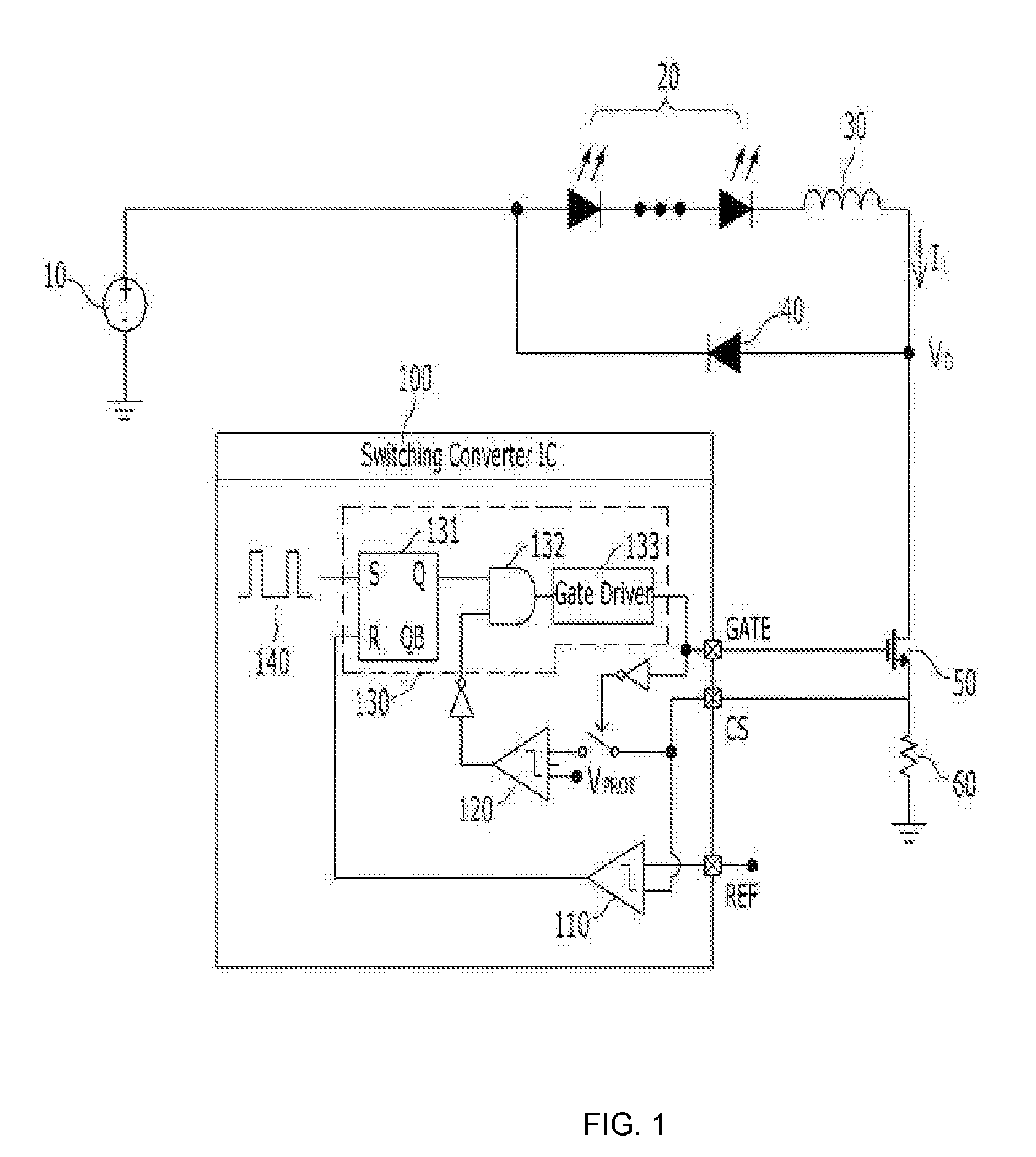
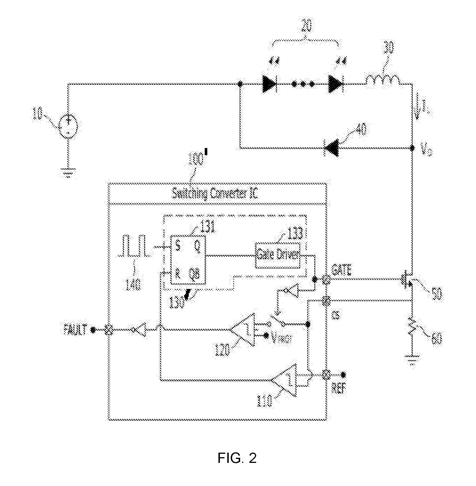
Leakage current detection circuit, light apparatus comprising the same and leakage current detection method

a leakage current and detection circuit technology, applied in the direction of lamps testing, fault locations, instruments, etc., can solve the problems of power mosfet burning or otherwise failing to function properly, voltage applied to the drain terminal of a power mosfet may exceed a limit, and leakage current may flow through the power mos

Active Publication Date: 2016-09-22
MAGNACHIP SEMICONDUCTOR LTD
View PDF1 Cites 11 Cited by
  • Summary
  • Abstract
  • Description
  • Claims
  • Application Information

AI Technical Summary

Benefits of technology

[0024]The leakage current detection circuit and / or the light apparatus having the same may maintain a driving voltage switch in an off state to prevent the driving voltage switch from burning or otherwise failing to function properly.

Problems solved by technology

When an abnormal situation occurs at a switching converter, a voltage applied to a drain terminal of a power MOSFET may exceed a limit and a leakage current may flow through the power MOSFET.
If the abnormal situation continues at the switching converter, the power MOSFET may burn or otherwise fail to function properly.
Therefore, an unfulfilled need exists for a leakage current detection apparatus and a method therefor that may prevent a driving voltage switch such as a power MOSFET from burning or otherwise failing to function properly during, for example, an abnormal situation.

Method used


Image

  • Leakage current detection circuit, light apparatus comprising the same and leakage current detection method
  • Leakage current detection circuit, light apparatus comprising the same and leakage current detection method
  • Leakage current detection circuit, light apparatus comprising the same and leakage current detection method

Examples


Embodiment Construction

[0034]The following detailed description is provided to assist the reader in gaining a comprehensive understanding of the methods, apparatuses, and / or systems described herein. The disclosure and the various features and advantageous details thereof are explained more fully with reference to the non-limiting embodiments and examples that are described and / or illustrated in the accompanying drawings and detailed in the following description. It should be noted that the features illustrated in the drawings are not necessarily drawn to scale, and features of one embodiment may be employed with other embodiments as the skilled artisan would recognize, even if not explicitly stated herein. Descriptions of well-known components and processing techniques may be omitted so as to not unnecessarily obscure the embodiments of the disclosure. The examples used herein are intended merely to facilitate an understanding of ways in which the disclosure may be practiced and to further enable those o...


PUM


Abstract

A leakage current detection circuit includes a driving voltage detection unit that detects a cut-off point of a driving voltage regulated through a driving voltage switch, a leakage current detection unit that detects a leakage current of the driving voltage switch after cutting off of the driving voltage, generates a leakage detection signal when a driving voltage related to the leakage current exceeds a reference detection voltage and a driving voltage control unit that turns off the driving voltage switch at a cut-off point of the driving voltage to cut off the driving voltage and maintain the driving voltage switch in an off state when the leakage detection signal is received. The leakage current detection circuit detects a leakage current passing through the driving voltage switch when abnormal operation of a light emitting diode light apparatus occurs, and keeps the driving voltage switch in an off state during cutoff periods to prevent burning of the drive voltage switch.

Description

CROSS-REFERENCE TO RELATED APPLICATION[0001]This application claims the benefit under 35 U.S.C. §119 of Korean Patent Application No. 10-2015-0036086, filed on Mar. 16, 2015, in the Korean Intellectual Property Office, the entire disclosure of which is incorporated herein by reference for all purposes.BACKGROUND OF THE DISCLOSURE[0002]1. Field of the Disclosure[0003]This disclosure relates to a method and an apparatus for driving a light apparatus, and, more particularly, a method and an apparatus for driving a leakage current detection circuit and a light apparatus having the same to detect a leakage current and control a driving voltage switch to prevent damage to the switch, for example.[0004]2. Description of Related Art[0005]An LED (Light Emitting Diode) light apparatus may be driven by means of a switching converter, such as, for example, a Buck-type, a Boost-type, or a Buck-Boost-type converter. Heretofore, Boost-type converters were mostly used. However, recently Buck-type c...

Claims


Application Information

Patent Timeline
Patent Type & Authority Applications(United States)
IPC IPC(8): H02H3/16H05B33/08H05B44/00
CPCH05B33/0815H02H3/16H02H7/1225H05B45/375H05B45/3725H05B45/38G01R19/165G01R31/08G01R31/44
Inventor SHIN, DOO SOOPARK, SU WANRYU, YOUNG GISHIN, YOUNG LOK
Owner MAGNACHIP SEMICONDUCTOR LTD
Why Eureka
Try Eureka