Combined device for power generation, power regulation, and removable power storage for a bicycle

a technology for electric power generation and bicycles, applied in cycle equipment, secondary cells, cell components, etc., to achieve the effects of improving rider safety, convenient removal, and increasing versatility

Inactive Publication Date: 2016-09-29
SIVA CYCLE
View PDF10 Cites 10 Cited by
  • Summary
  • Abstract
  • Description
  • Claims
  • Application Information

AI Technical Summary

Benefits of technology

[0034]Another objective of the innovation is to allow the generator to be removed easily from the mount with a quick release mechanism, protecting against theft of the device. This easy removability feature overcomes the shortcoming of prior art outlined above in 3e.
[0035]An additional objective of the innovation is to provide integrated rear lighting in order to improve rider safety by incorporating lights that do not require replaceable batteries. The lights are engaged by light sensors or a switch.
[0036]Another objective of the innovation is to provide a rotational input mechanism that can mount to any spoke configuration of the turning input entity that doubles as a clutch mechanism for protection against rapid acceleration and deceleration of the rotating input entity. This allows increased versatility of the innovation, allowing it to mount quickly and without tools and transfer rotational energy from a wide variety of rotating input surfaces. The clutch mechanism of the innovation protects both the rotating entity from damage during rapid acceleration or deceleration, as well as the internal components of the innovation itself. This objective addresses the shortcomings of prior art outlined above in 3g.

Problems solved by technology

First, external sidewall generators generate power by utilizing the friction between the sidewall of the bicycle wheel and the generator's rotor contact wheel to cause the rotation of the rotor relative to the stator.
Second, hub generators generate power by utilizing the rotation of the bicycle wheel to cause the rotation of the rotor of the generator relative to the stator.
1. Sidewall Bicycle Generatora. Friction based transfer of motion is susceptible to environmental (such as weather) and hardware (such as tire rubber compound) based variables that greatly affect its ability to consistently performb. Accurate alignment is needed for efficient transfer of motion and consistent performancec. Generator body or mount typically extends outside the confines of the bicycle frame, increasing the chance of damage or destruction by impact, also increases likelihood of generator being knocked out of alignmentd. The electrical output is not regulated for use with personal electronics and requires additional accessories that require extensive knowledge to implement.e. There is no electrical storage (battery) available to capture generated power for later use.
2. Hub Bicycle Generatora. Due to the nature of this device having to serve as the entity of the wheel center with the necessary precision and robustness, cost is typically high.b. Cost to the consumer is further increased by the need to then build or assemble a wheel around the generator hub, a highly skilled task.c. By being directly linked to the rotational speed of the bicycle wheel and given requested performance at low bicycle velocities, the generator becomes heavy for the desired power output at certain speeds.d. The electrical output is not regulated for use with personal electronics and requires additional accessories that require extensive knowledge to implement.e. There is no electrical storage (battery) available to capture generated power for later use.f. There is no way to disengage the generator from the bicycle when not in use. This means that the inherent drag of the core loss of the generator stator will always be present to the user, taxing their ride even when the generator is not creating electrical power.
3. Existing External, Bicycle Axel-mounted Generatorsa. If there is electrical storage, it is not detachable for use away from bicycle.b. Output for external powering of electronic devices limited to a single output value and format.c. No auxiliary method of charging the electrical storage device. Only power from the generator is available as a charging method.d. Does not accept any other method of power input for output options other than the input from the integrated generator or onboard battery. Only input from the integrated generator can charge the onboard battery or create an output to power external electronics.e. Generator is not detachable from bicycle for protection from theft.f. Does not fit within the confines of the bicycle frame creating risk of damage or destruction by contact with surrounding environment.g. Uses direct interference or mounting to the rotating input wheel spokes in order to draw rotational energy that, in turn, spins the generator. This risks the following: damaging of the turning entity spokes in an event of rapid acceleration or deceleration; damaging of the internal components of the generating device during rapid acceleration or deceleration; limits mounting opportunities of the generating device to those turning entities that have spokes of a certain spacing, number, and size.

Method used


Image

  • Combined device for power generation, power regulation, and removable power storage for a bicycle
  • Combined device for power generation, power regulation, and removable power storage for a bicycle
  • Combined device for power generation, power regulation, and removable power storage for a bicycle

Examples


Embodiment Construction

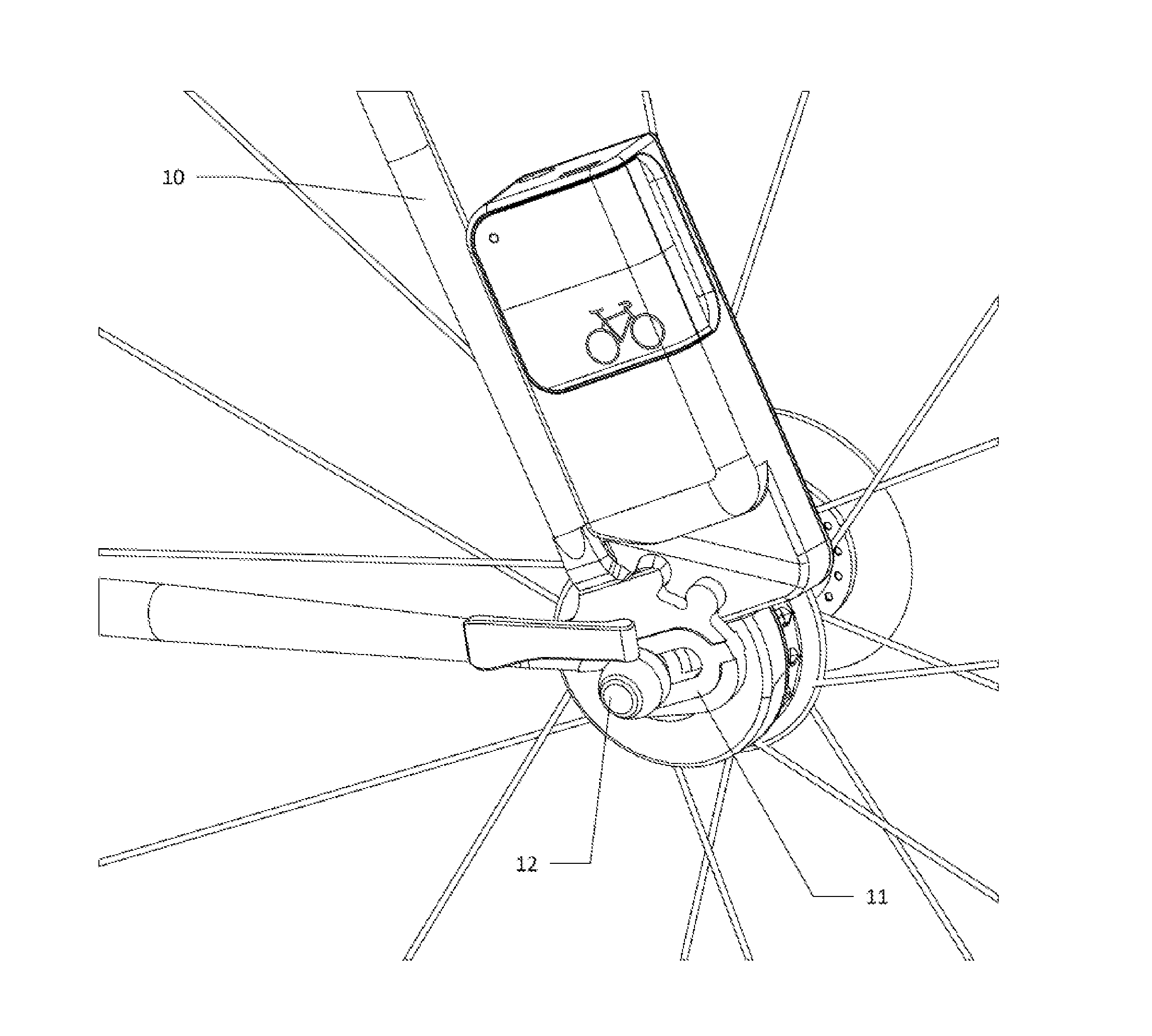
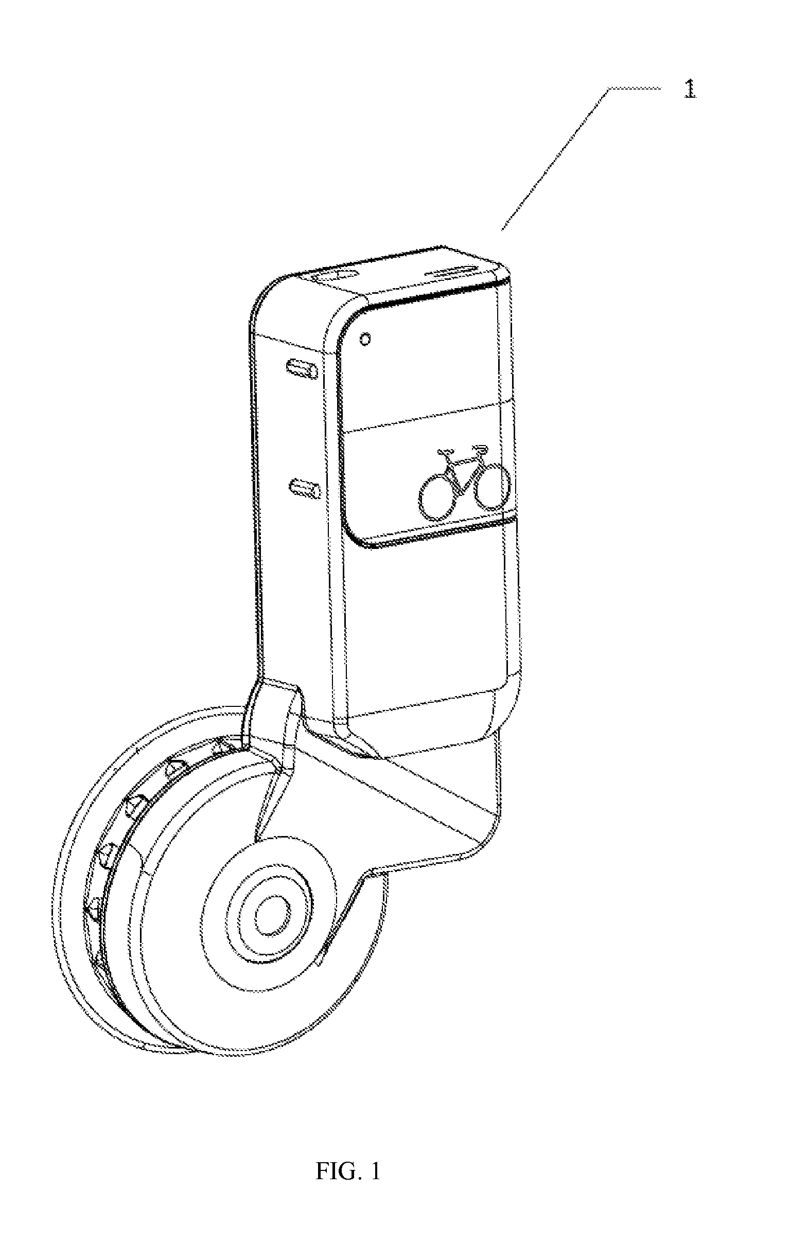
[0054]Referring now to the invention in more detail, in FIG. 1 there is the present invention 1 in its complete form, uninstalled on a bicycle.

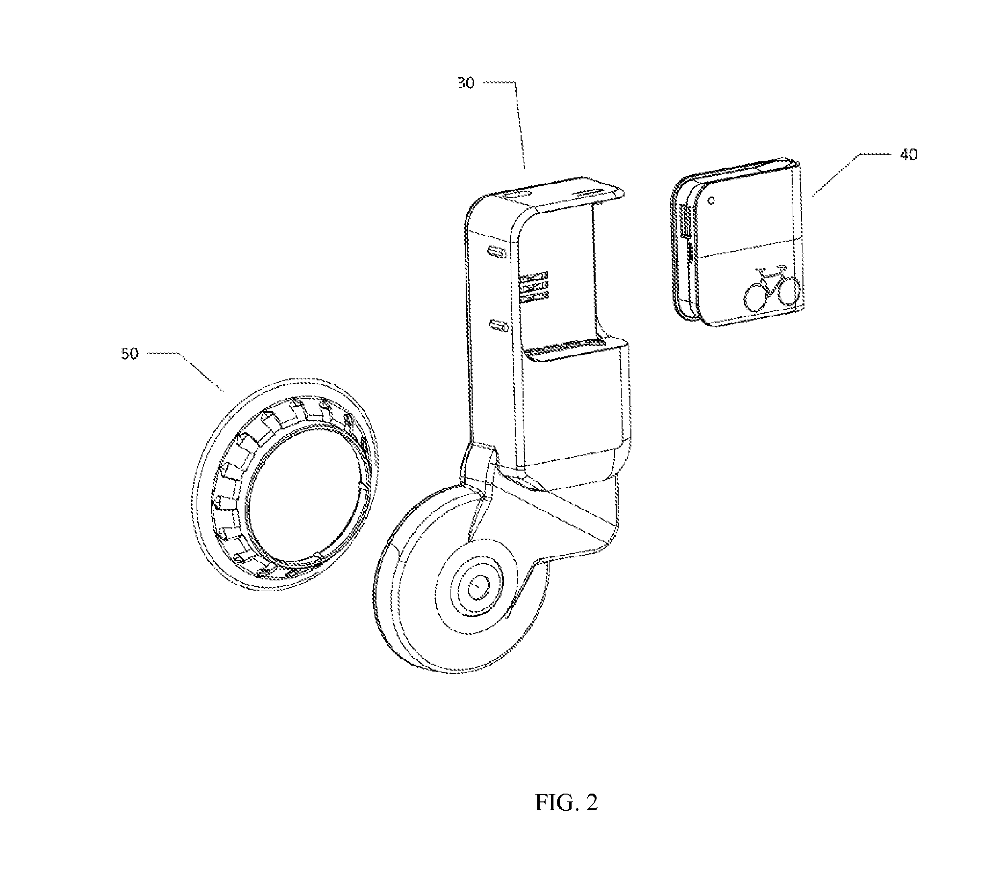
[0055]Referring to FIG. 2, we see that the present invention 1 in complete form is comprised of three sub-assemblies immediately removable: the main housing 30, the detachable battery 40, and the rotational input mechanism 50.

[0056]Referring to FIG. 3, we see the main housing 30 in complete form, of note are the battery contacts 33, and housing power outlet 36.

[0057]Referring to FIG. 4, we see the main housing in exploded form, of note is the mechanical assembly 60, housing shell 31, housing lid 32, battery contacts 33, and generator ECU 35.

[0058]Referring to FIG. 5, we see the mechanical assembly 60 from the front and rear views. Of note is the primary drive gear 64, the gear train housing right 65, the gear train housing left 66, and the frame clamp 67.

[0059]Referring to FIG. 6, we see the gear train assembly 61, which consists of the rotor...


PUM


Abstract

A combined device for power generation, power regulation, and removable, rechargeable, power storage for a bicycle comprising of: a main housing, a primary drive gear located inside the main housing, said primary drive gear positioned on a bicycle such that the turning of the bicycle wheel turns the primary drive gear, a gear drive system having a rotor gear, an electronics module containing a plurality of electronic components to convert electrical input forms into a electrical output forms of preference, a rechargeable battery pack, a power output jack located on the removable battery pack housing, a hub mount that is clamped between a bicycle hub and a bicycle frame dropout by a clamping mechanism.

Description

CROSS-REFERENCE TO RELATED APPLICATIONS[0001]This application claims priority from U.S. Provisional 61 / 804,381 titled Combined Device for Power Generation, Power Regulation, and Removable Power Storage for a Bicycle, filed on Mar. 22, 2013BACKGROUND OF THE INVENTION[0002]The present invention is in the technical field of electricity generators.[0003]More particularly, the present invention is in the technical field of electricity generators for bicycles.[0004]Existing generators for bicycles fall into three categories. First, external sidewall generators generate power by utilizing the friction between the sidewall of the bicycle wheel and the generator's rotor contact wheel to cause the rotation of the rotor relative to the stator. Second, hub generators generate power by utilizing the rotation of the bicycle wheel to cause the rotation of the rotor of the generator relative to the stator. Third, bicycle axel mounted, external generators generate power by utilizing the mechanical t...

Claims


Application Information

Patent Timeline
Patent Type & Authority Applications(United States)
IPC IPC(8): B62J6/12H01M2/10B62J6/10H01M10/42H01M50/204H01M50/249H01M50/284
CPCB62J6/12H01M10/4257H01M2010/4271H01M2/1083B62J6/10H01M2/1077B62J6/14Y02E60/10H01M50/204H01M50/249H01M50/284B62J6/06
Inventor LATZKE, AARON
Owner SIVA CYCLE
Why Eureka
Try Eureka