Artificial-photosynthesis array

a technology of artificial photosynthesis and arrays, which is applied in the direction of electrode coating, final product manufacturing, sustainable manufacturing/processing, etc., can solve the problems of difficult to keep the ion concentration or ph value constant in water, the ability of water decomposition to degrade, and the difficulty of hydrogen gas and oxygen gas separation

Inactive Publication Date: 2016-09-29
FUJIFILM CORP +2
View PDF5 Cites 6 Cited by
  • Summary
  • Abstract
  • Description
  • Claims
  • Application Information

AI Technical Summary

Benefits of technology

[0011]An object of the invention is to solve the problem based on the related art and to provide an artificial-photosynthesis array that can reduce mixing of hydrogen gas and oxygen gas and can keep an ion concentration or pH value in water constant.
[0019]According to the invention, by devising the connection form of the plurality of artificial-photosynthesis modules, the ion concentration or pH value in water can be kept constant, and mixture of the hydrogen gas and the oxygen gas can be prevented.

Problems solved by technology

Meanwhile, if water continues being decomposed, a difference is caused in ion concentration or pH value in water between the hydrogen generating part and the oxygen generating part, and water decomposition capability degrades.
However, in a case where a space is partitioned off by such a membrane, there is a problem that it is difficult to separate the hydrogen gas and the oxygen gas completely to prevent mixture of the hydrogen gas and the oxygen gas, and it is difficult to keep the ion concentration or pH value in water constant.

Method used


Image

  • Artificial-photosynthesis array
  • Artificial-photosynthesis array
  • Artificial-photosynthesis array

Examples


second embodiment

[0128]Next, the invention will be described.

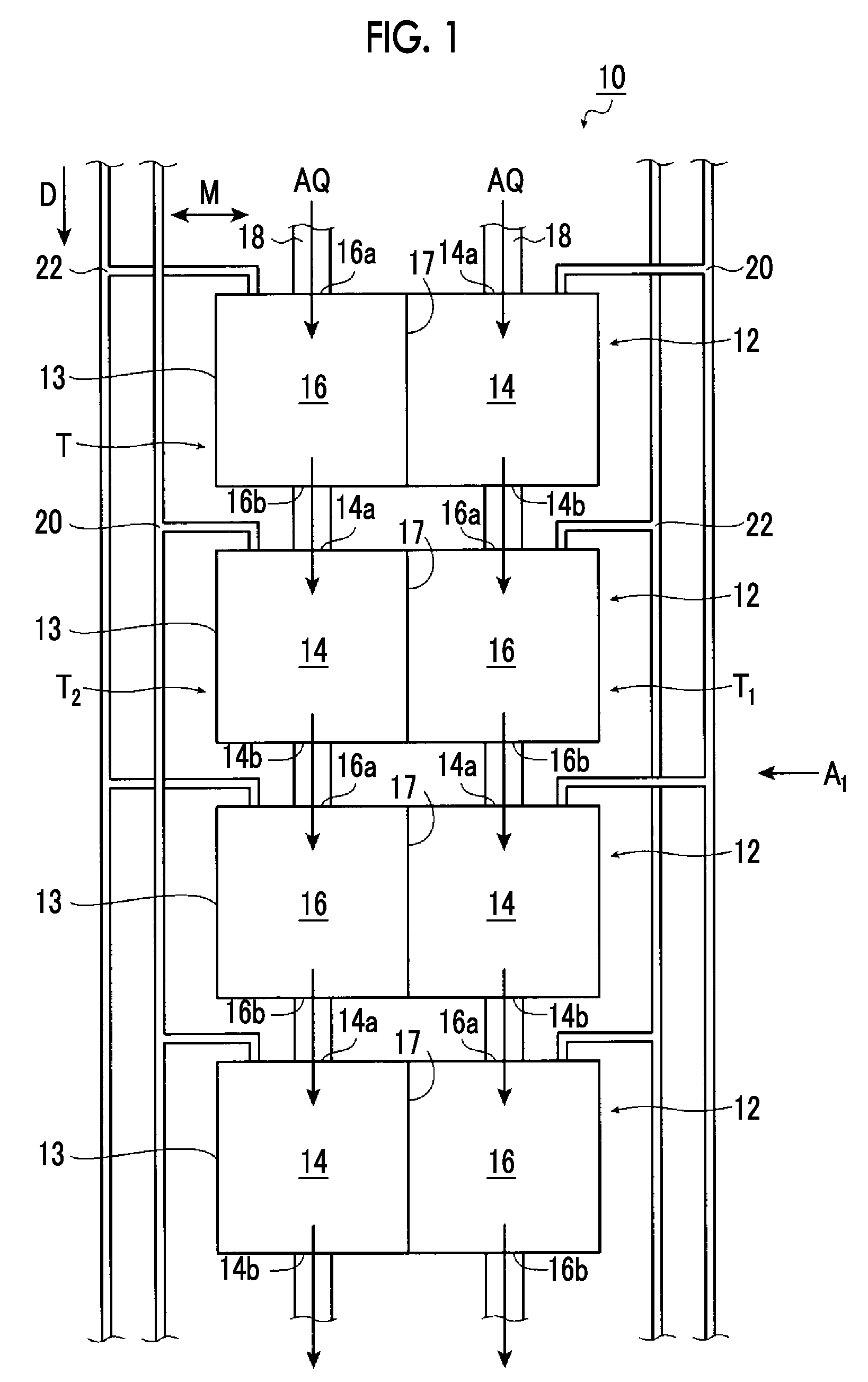
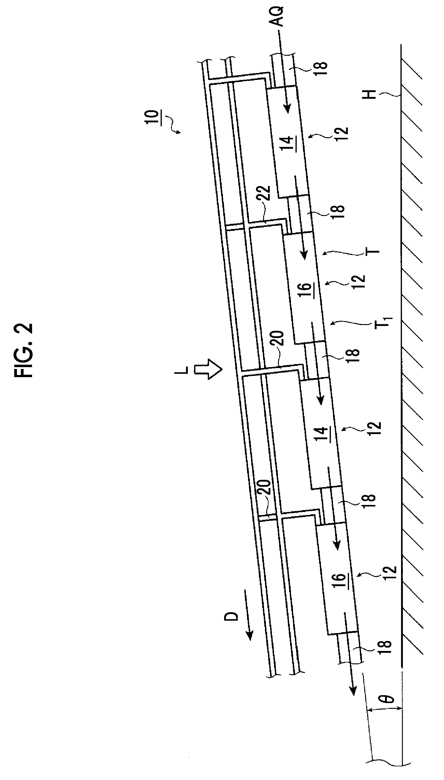
[0129]FIG. 6 is a schematic plan view illustrating an artificial-photosynthesis array of a second embodiment of the invention, and FIG. 7 is a side view of an artificial-photosynthesis array of the second embodiment illustrated in FIG. 6. In addition, FIG. 7 is a side view when an artificial-photosynthesis array 10a illustrated in FIG. 6 is seen from direction A3.

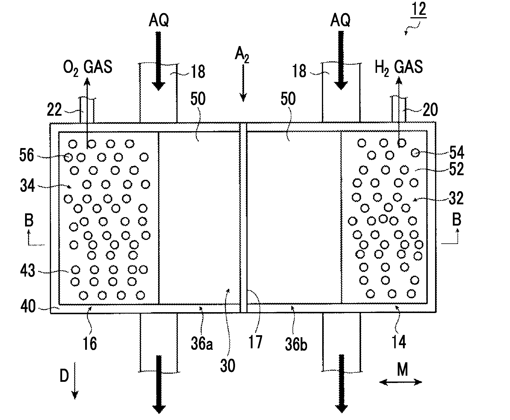
[0130]In the artificial-photosynthesis array 10a of the present embodiment, the same structures as those of the artificial-photosynthesis array 10 illustrated in FIGS. 1 and 2 will be designated by the same reference signs, and the detailed description thereof will not be described. Additionally, the artificial-photosynthesis array 10a has artificial-photosynthesis modules 60. In each artificial-photosynthesis module 60, the same structures as those of the artificial-photosynthesis module 12 illustrated in FIGS. 3 to 5 will be designated by the same reference signs, and the detail...

first embodiment

[0143]Additionally, in the method for manufacturing the artificial-photosynthesis module 60, the detailed description of the same processes as those of the method for manufacturing the artificial-photosynthesis module 12 of the first embodiment will be omitted.

[0144]In the method for manufacturing the artificial-photosynthesis module 60, since a process of forming the protective layer 50 and forming the photoelectric conversion unit 30 and a process of forming the functional layer 52 and forming the co-catalyst 54 for generation of hydrogen on the functional layer 52 are the same processes as those of the method for manufacturing the artificial-photosynthesis module 12 except for a process of first preparing a soda lime glass substrate that becomes the insulating substrate 40, and then providing the partition wall 17, the detailed description thereof will be omitted.

[0145]Thereafter, the insulating substrate 40 and the back electrode 42 at the position equivalent to the photoelectri...


PUM

PropertyMeasurementUnit
overvoltageaaaaaaaaaa
thicknessaaaaaaaaaa
thicknessaaaaaaaaaa

Abstract

Provided is an artificial-photosynthesis array configured of artificial-photosynthesis modules which have been arranged in one or more rows and which receive light and decompose a supplied aqueous electrolyte solution to thereby obtain hydrogen gas and oxygen gas. The artificial-photosynthesis modules each includes an electrolytic chamber for hydrogen where hydrogen gas is generated and an electrolytic chamber for oxygen where oxygen gas is generated, the chambers being isolated from each other. The electrolytic chambers for hydrogen and electrolytic chambers for oxygen of the artificial-photosynthesis modules are alternately connected so that the electrolytic chamber for hydrogen of each artificial-photosynthesis module is connected to the electrolytic chamber for oxygen of another module and the electrolytic chamber for oxygen of each artificial-photosynthesis module is connected to the electrolytic chamber for hydrogen of another module.

Description

CROSS-REFERENCE TO RELATED APPLICATIONS[0001]This application is a Continuation of PCT International Application No. PCT / JP2014 / 080943 filed on Nov. 21, 2014, which claims priority under 35 U.S.C. §119(a) to Japanese Patent Application No. 2013-258305 filed on Dec. 13, 2013. The above application is hereby expressly incorporated by reference, in its entirety, into the present application.BACKGROUND OF THE INVENTION[0002]1. Field of the Invention[0003]The present invention relates to an artificial-photosynthesis array that has a plurality of artificial-photosynthesis modules that receive light to decompose water and manufacture hydrogen and oxygen, and particularly, to an artificial-photosynthesis array that can keep an ion concentration or pH value in water constant.[0004]2. Description of the Related Art[0005]In the related art, as one form of using solar light energy that is a renewable energy, there are suggested hydrogen manufacturing apparatuses that utilize electrons and posit...

Claims


Application Information

Patent Timeline
Patent Type & Authority Applications(United States)
IPC IPC(8): C25B1/10C25B9/08H01L31/0749C25B15/08H01L31/042H01L31/032C25B1/00C25B11/04C25B9/19
CPCC25B1/10C25B1/003C25B9/08C25B11/0473H01L31/0749H01L31/042H01L31/0322H01L31/0326C25B15/08C25B15/00C25B1/04Y02E10/541Y02E60/36Y02P70/50C25B1/55C25B9/73C25B9/19C25B11/081
Inventor SATO, NAOTOSHIDOMEN, KAZUNARITSUKAHARA, JIRO
Owner FUJIFILM CORP
Why Eureka
Try Eureka