Optical transmission module

a technology of optical transmission module and optical transmission element, which is applied in the direction of optical elements, instruments, optical radiation measurement, etc., can solve the problems of difficult control of the intensity of light emitted, inability of light-receiving elements to obtain precise monitoring, etc., and achieve the effect of more constan

Active Publication Date: 2016-09-29
LUMENTUM JAPAN INC
View PDF1 Cites 8 Cited by
  • Summary
  • Abstract
  • Description
  • Claims
  • Application Information

AI Technical Summary

Benefits of technology

[0010]It is an object of the invention to provide an optical transmission module provided with a plurality of light-emitting elements and a plurality of light-receiving elements, in which each of the plurality of light-receiving elements accurately monitors light emitted from the light-emitting element, and thus the intensities of the lights emitted from the plurality of light-emitting elements are controlled so as to be more constant.

Problems solved by technology

When the leakage light or the like described above is incident on the light-receiving element, the light-receiving element cannot obtain a precise monitoring result.
As a result, it may become difficult to control the intensity of the light emitted from the one light-emitting element so as to be constant.

Method used


Image

  • Optical transmission module
  • Optical transmission module
  • Optical transmission module

Examples


first embodiment

[0028]First, an outline of an optical transmission module according to a first embodiment of the invention will be described with reference to FIGS. 1 to 3.

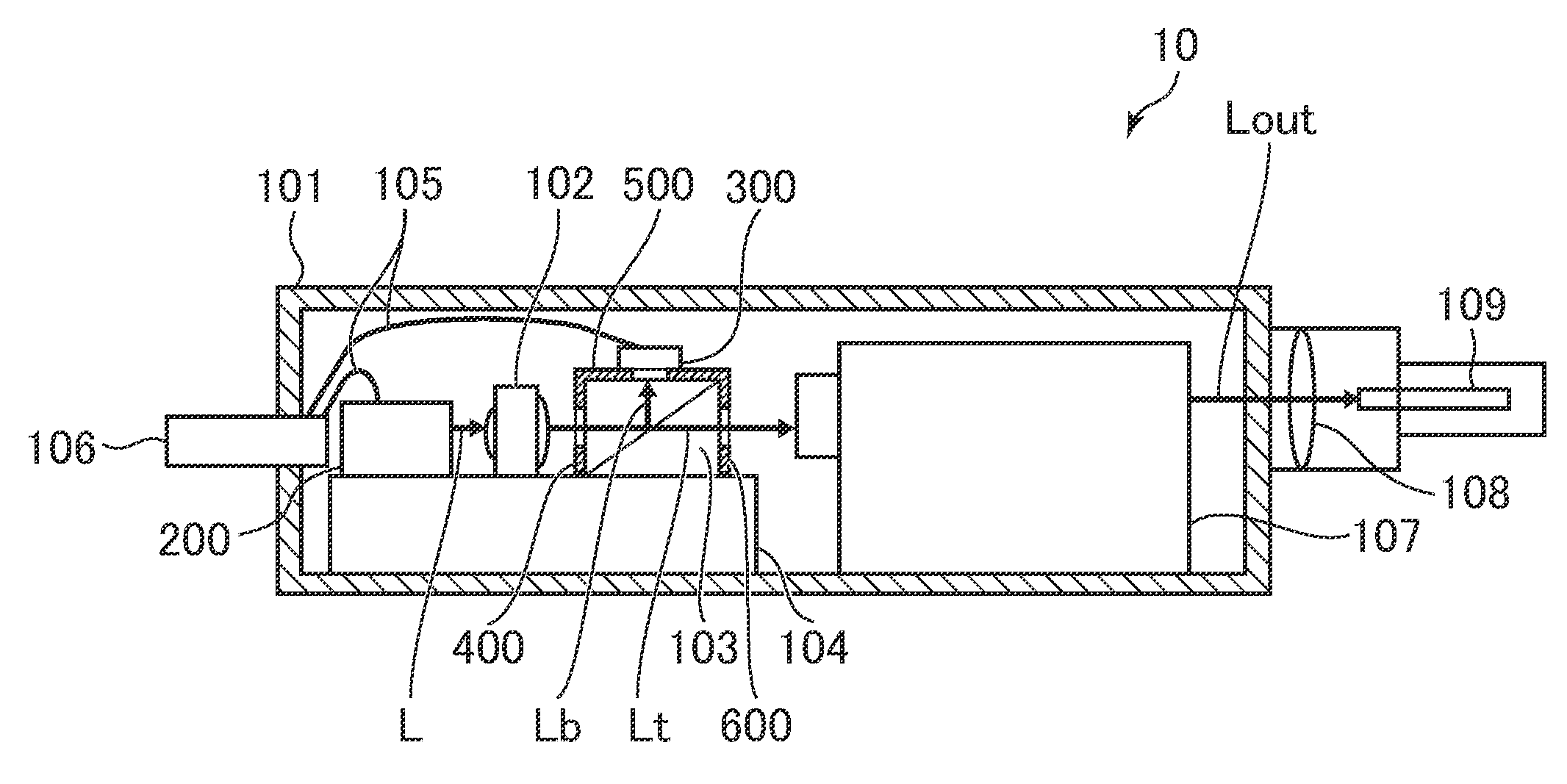
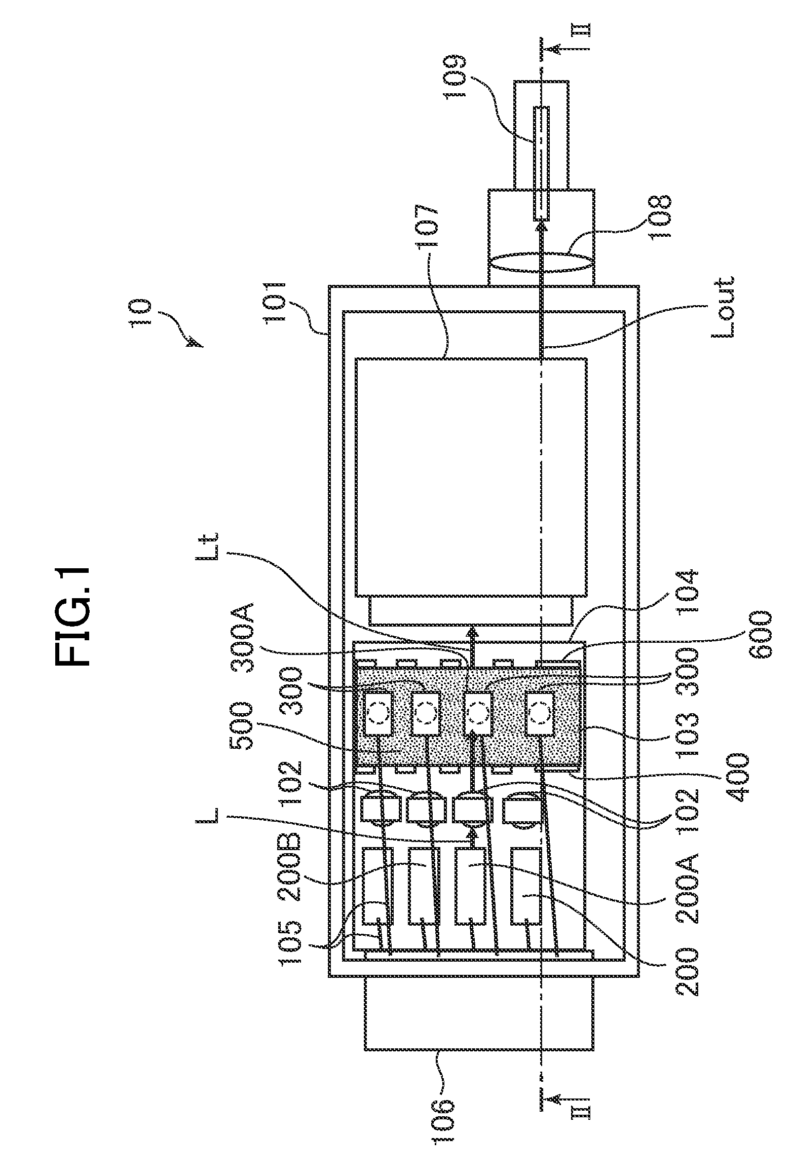
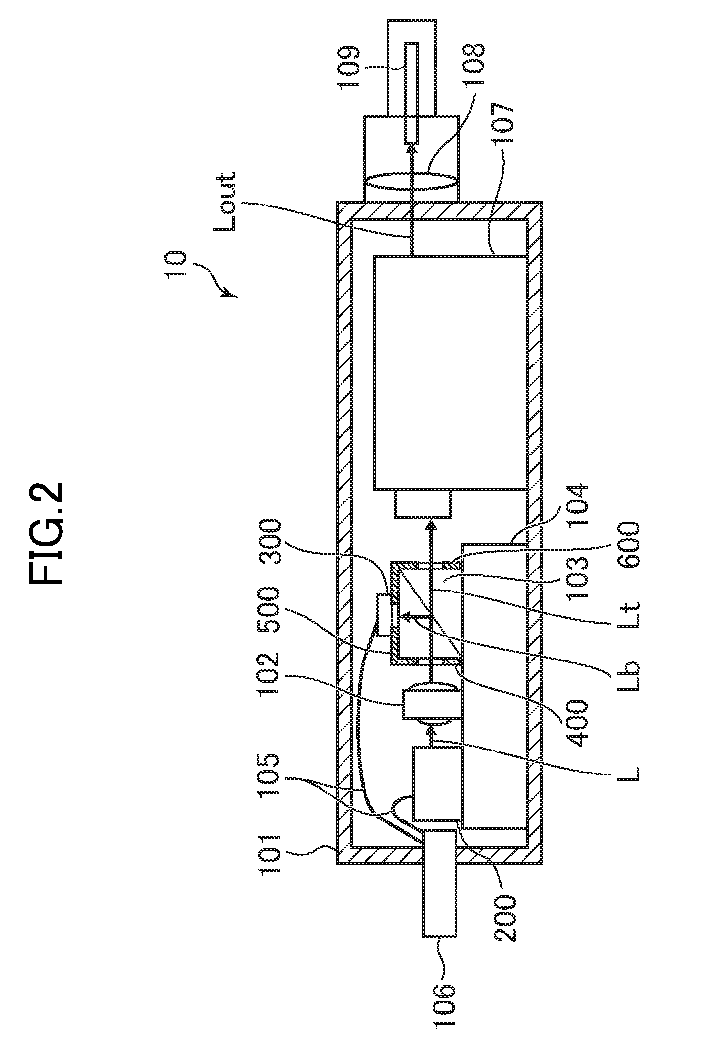
[0029]FIG. 1 is a diagram showing the state of the interior of the optical transmission module according to the first embodiment of the invention, viewed from above. FIG. 2 is a diagram showing a cross-section along the section line II-II in FIG. 1, showing the configuration of the optical transmission module according to the first embodiment. FIG. 3 is a perspective view showing a beam splitter used for the optical transmission module according to the first embodiment.

[0030]The optical transmission module 10 according to the first embodiment includes: a package 101; a plurality of light-emitting elements 200 each emitting light L by space transmission in the interior of the package 101; a beam splitter (optical demultiplexer) 103 splitting the light L into transmitted light Lt and split light Lb; a repeater 107 for guiding the t...

second embodiment

[0073]Hereinafter, an outline of an optical transmission module 20 according to a second embodiment of the invention will be described with reference to FIGS. 4 and 5. Configurations having the same functions as those of the optical transmission module 10 according to the first embodiment in FIGS. 1 and 2 are denoted by the same reference numerals and signs in FIGS. 4 and 5.

[0074]FIG. 4 is a diagram showing the state of the interior of the optical transmission module according to the second embodiment of the invention, viewed from above. FIG. 5 is a diagram showing a cross-section along the section line V-V in FIG. 4, showing the configuration of the optical transmission module according to the second embodiment.

[0075]The optical transmission module 20 according to the second embodiment is different from the optical transmission module 10 according to the first embodiment described above in that the first, second, and third light-shielding films are not directly formed on the beam s...


PUM


Abstract

An optical transmission module includes: a package; a plurality of light-emitting elements each emitting light in the interior of the package; a beam splitter splitting the light into transmitted light and split light; a plurality of light-receiving elements each including a light-receiving surface on which the split light is incident in the interior of the package, for monitoring light outputs of the plurality of light-emitting elements; and a first light-shielding film provided between the plurality of light-emitting elements and the beam splitter and including a plurality of first holes for the light to propagate to the beam splitter, wherein the plurality of light-receiving elements are disposed with the light-receiving surfaces facing the beam splitter.

Description

CROSS-REFERENCE TO RELATED APPLICATION[0001]The present application claims priority from Japanese application JP2015-062108 filed on Mar. 25, 2015, the content of which is hereby incorporated by reference into this application.BACKGROUND OF THE INVENTION[0002]1. Field of the Invention[0003]The present invention relates to an optical transmission module.[0004]2. Description of the Related Art[0005]JP 2013-148825 A discloses an optical module.[0006]An optical transmission module that converts an electric signal to an optical signal and outputs the optical signal is provided with a light-receiving element for monitoring light emitted from a light-emitting element. The light-receiving element monitors a light output emitted from the light-emitting element, and the optical transmission module controls, based on the monitoring result, the intensity of the light emitted from the light-emitting element so as to be constant.[0007]It is considered that an optical transmission module provided ...

Claims


Application Information

Patent Timeline
Patent Type & Authority Applications(United States)
IPC IPC(8): G01J1/02G01J1/04G02B6/42
CPCG01J1/0214G02B6/4286G01J1/0414G01J1/0411G01J1/0204G01J1/0271
Inventor HASEGAWA, TAKAYUKIMURAKAMI, DAISUKEYAMASHITA, TAKESHI
Owner LUMENTUM JAPAN INC
Why Eureka
Try Eureka