Calibration scheme for improving flexibility on platform implementation
a platform and flexibility technology, applied in the direction of instruments, liquid/fluent solid measurement, power supply for data processing, etc., can solve the problems of high bandwidth requirements, complex interconnection architecture, and mobile devices sacrificing overall performance for power savings
- Summary
- Abstract
- Description
- Claims
- Application Information
AI Technical Summary
Benefits of technology
Problems solved by technology
Method used
Image
Examples
example 1
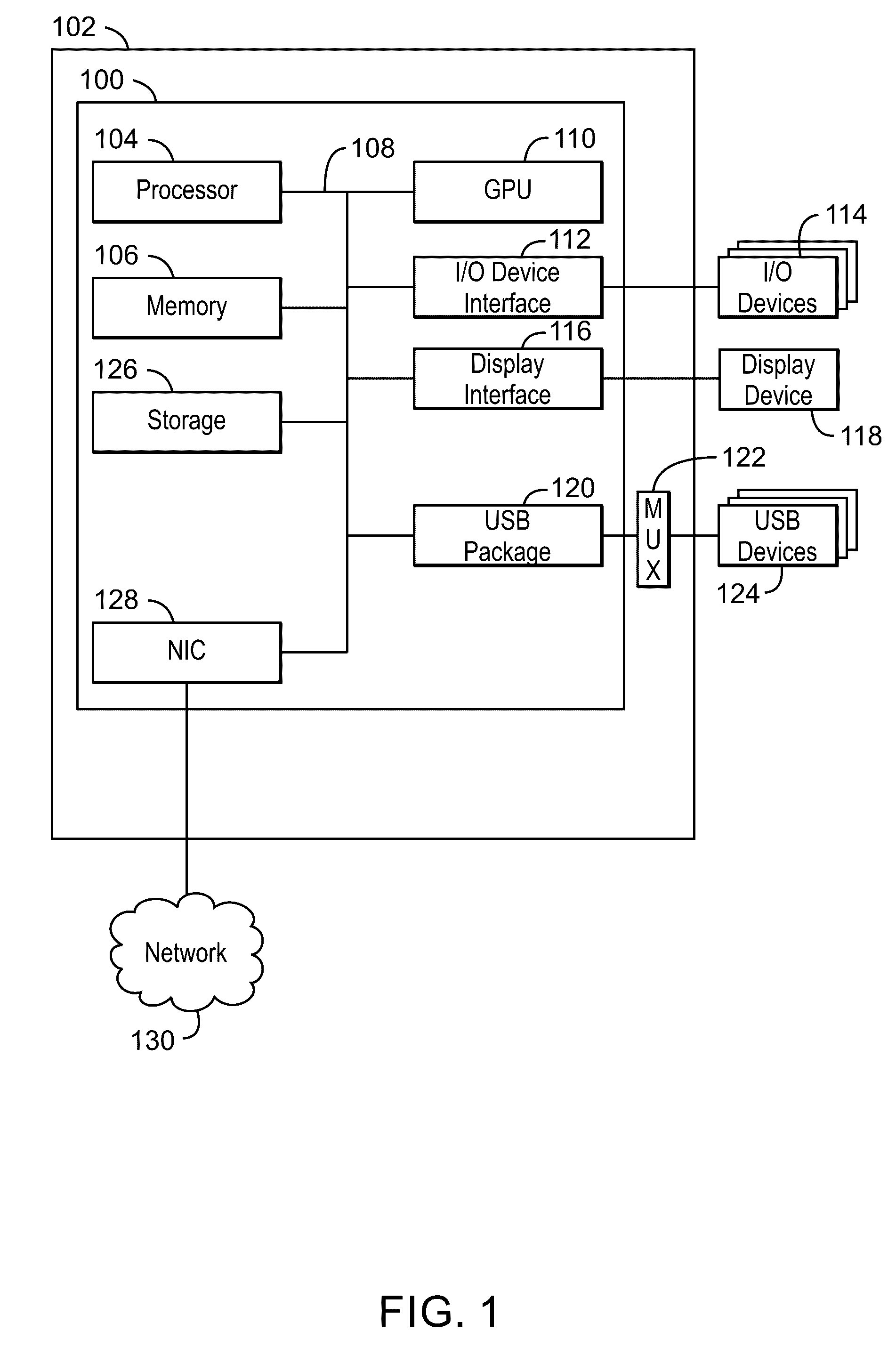
[0069]An apparatus is described herein. The apparatus includes a high speed pull up driver and a comparator. The high speed pull-up driver has a variable output impedance. The comparator is coupled to the high speed pull-up driver, and is to compare an output voltage of the high speed pull-up driver to a reference voltage, and to signal a result of the comparison to a finite state machine, the finite state machine to select the reference voltage for the comparison and to control the output impedance of the high speed pull-up driver based on the result of the comparison and the selected reference voltage.
[0070]The apparatus may include additional impedance from a plurality of electrical components, wherein the output impedance is controlled based on the additional impedance. The output impedance may be controlled to be approximately 45 ohms. Detection of the output impedance may occur when a driver termination exists. The reference voltage may to correspond to a platform resistance v...
example 2
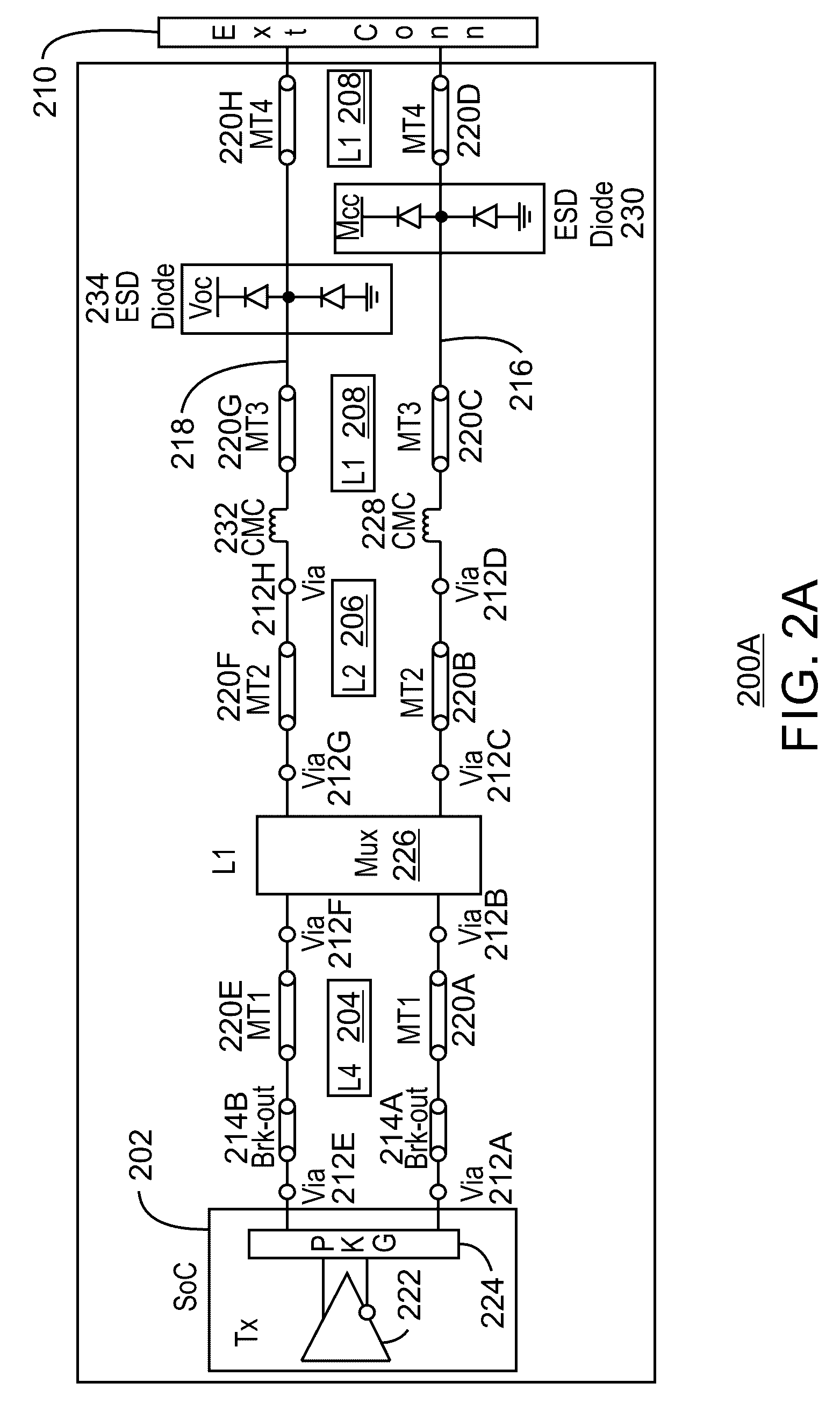
[0071]A system is described herein. The system includes a device. The device is to couple with a host, and in response to the device being coupled with the host, a platform resistance detection is performed where a reference voltage that is to drive an output of a comparator high is mapped to a corresponding resistance compensation value to be applied to a pull up resistance of the host.
[0072]A finite state machine may determine the reference voltage that is to drive an output of a comparator high via a reference voltage table. The platform resistance may be a resistance as measured at a connector of the device during a chirp event. The platform resistance can be adjusted to be approximately 45 ohms. The detection of the resistance can occur when a driver termination exists. The platform resistance may be adjusted based on the reference voltage and a look up table for platform resistance compensation. The look up table values can be computed using a voltage divider concept. Platform...
example 3
[0073]A method is described herein. The method includes estimating a first voltage level and adjusting a reference voltage level until a comparator is tripped, wherein the first voltage level and the reference voltage are inputs to the comparator. The method also includes determining platform resistance based on the adjusted reference voltage and adjusting the platform resistance to maintain high speed data integrity.
[0074]The first voltage level may be Vbump. The first voltage level may also be estimated using a voltage divider concept. Platform resistance may be determined during a chirp event. Adjustments and platform resistance determination may be performed when a device physical layer (PHY) pull-down termination occurs and a host continues to drive a low frequency Chirp K-J signal. A reference voltage may be re-adjusted at a plurality of receivers. The platform resistance can be adjusted by offsetting bits of a pull-up resistor. A lookup table is used to determine the number o...
PUM
 Abstract
Description
Claims
Application Information
 - R&D
- Intellectual Property
- Life Sciences
- Materials
- Tech Scout
- Unparalleled Data Quality
- Higher Quality Content
- 60% Fewer Hallucinations
Browse by: Latest US Patents, China's latest patents, Technical Efficacy Thesaurus, Application Domain, Technology Topic, Popular Technical Reports.
© 2025 PatSnap. All rights reserved.Legal|Privacy policy|Modern Slavery Act Transparency Statement|Sitemap|About US| Contact US: help@patsnap.com


