
Substrate holding method and substrate processing apparatus

a substrate and holding method technology, applied in the direction of electric devices, conveyor parts, transportation and packaging, etc., can solve the problems of difficult steps and achieve the effect of short time and difficult to reduce the size of the substrate processing apparatus

Active Publication Date: 2016-09-29
DAINIPPON SCREEN MTG CO LTD
View PDF0 Cites 6 Cited by
  • Summary
  • Abstract
  • Description
  • Claims
  • Application Information

AI Technical Summary

Benefits of technology

This patent text is about a method and apparatus for holding and processing substrates. The technical effects of this invention are that it allows for sandwiching a substrate from a horizontal direction using a simple arrangement, without requiring horizontal support pins and a mechanism to move them. This makes it difficult to reduce the size of the substrate processing apparatus. Additionally, the method involves bringing the positioning pin into a closed state to serve as a positioning standard of the substrate with respect to the spin base, thereby securing high positioning accuracy when the substrate is held by the spin chuck. Furthermore, this arrangement reduces the number of steps required and the mechanism needed to temporarily place the substrate on a horizontal support pin.

Problems solved by technology

Therefore, the horizontal support pins and a mechanism to move these pins are needed, thus making it difficult to reduce the substrate processing apparatus in size.
Also, a step of placing the lower portion of the substrate at the horizontal support pins before sandwiching the substrate therebetween is indispensable, and therefore it is difficult to perform steps ranging from the transfer of the substrate to the sandwich of the substrate from its side surface in a short time.

Method used


Image

  • Substrate holding method and substrate processing apparatus
  • Substrate holding method and substrate processing apparatus
  • Substrate holding method and substrate processing apparatus

Examples


Embodiment Construction

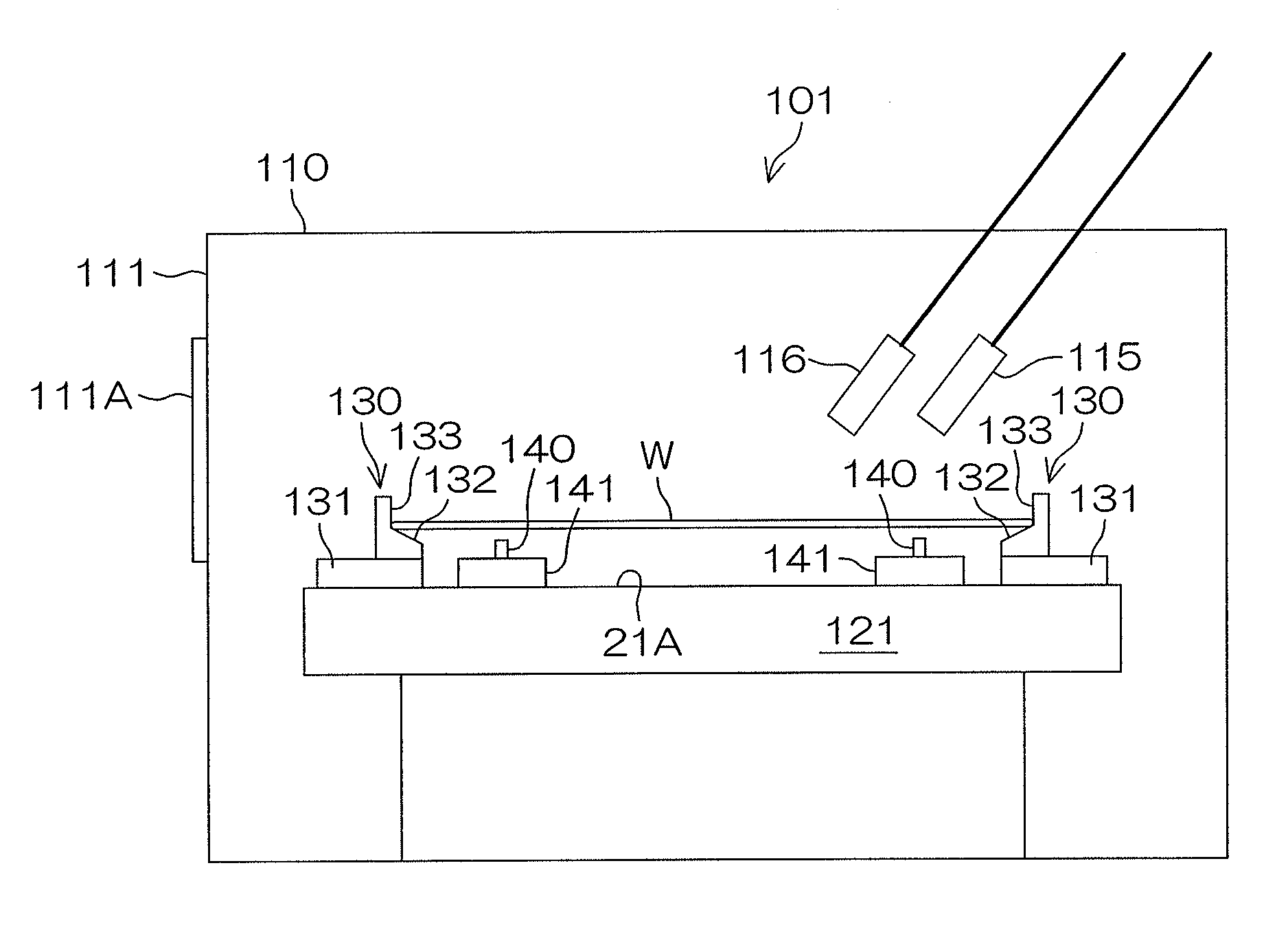
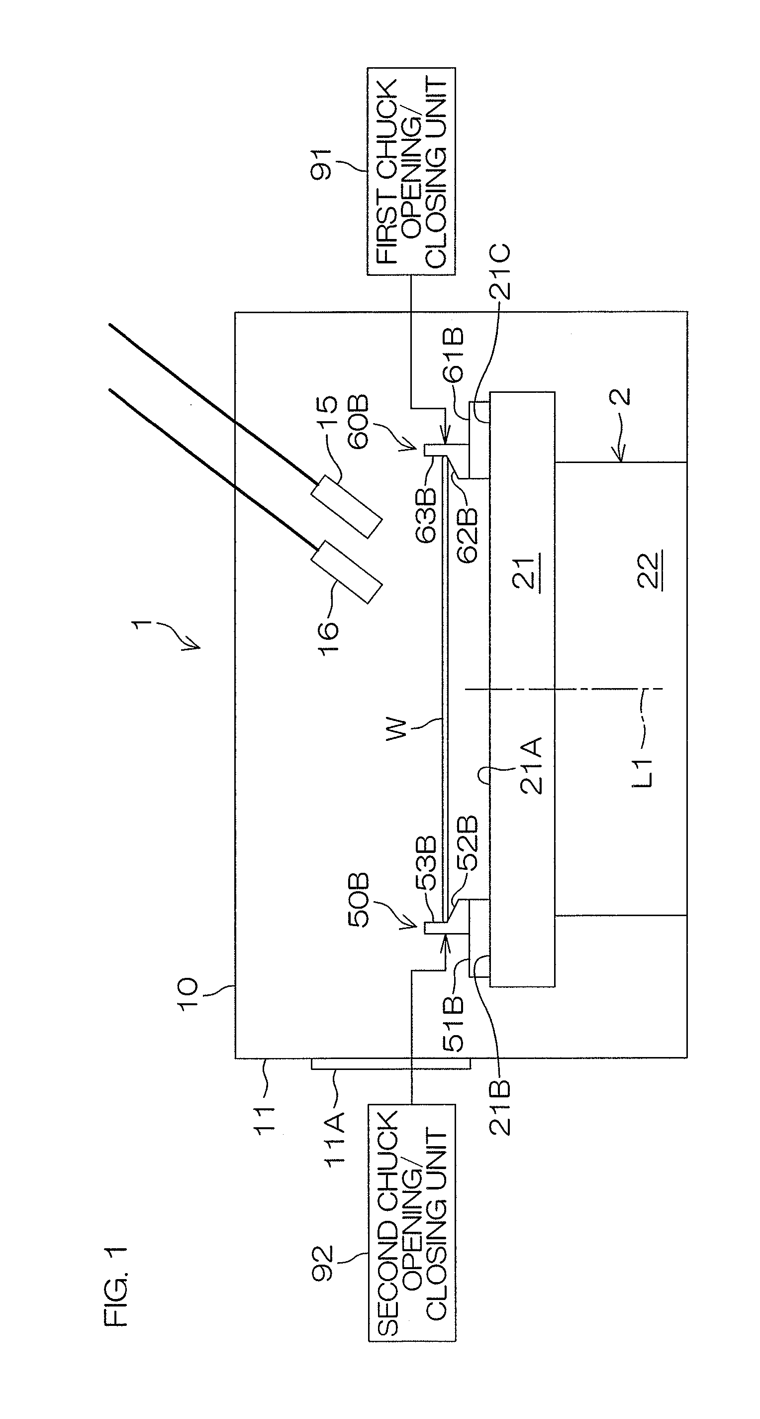
[0039]FIG. 1 is a side view showing a schematic arrangement of a substrate processing apparatus 1 according to a preferred embodiment of the present invention. The substrate processing apparatus 1 includes a processing chamber 10 surrounded by a chamber wall 11. The processing chamber 10 includes a spin chuck 2 (substrate holding / rotating device). A shutter portion 11A having an openable / closable opening is disposed at the side surface of the chamber wall 11. A hand mechanism 6 of a substrate transfer mechanism 5 shown in FIG. 5 is allowed to move back and forth through the opening.

[0040]The substrate processing apparatus1 further includes a processing liquid nozzle 15 and / or a gas nozzle 16. The processing liquid nozzle 15 or the gas nozzle 16 is ordinarily in a retreated state at a retreat position except when substrates are processed, and is moved by a moving mechanism (not shown) to a predetermined position above a substrate W when substrates are processed.

[0041]The spin chuck 2...


PUM


Abstract

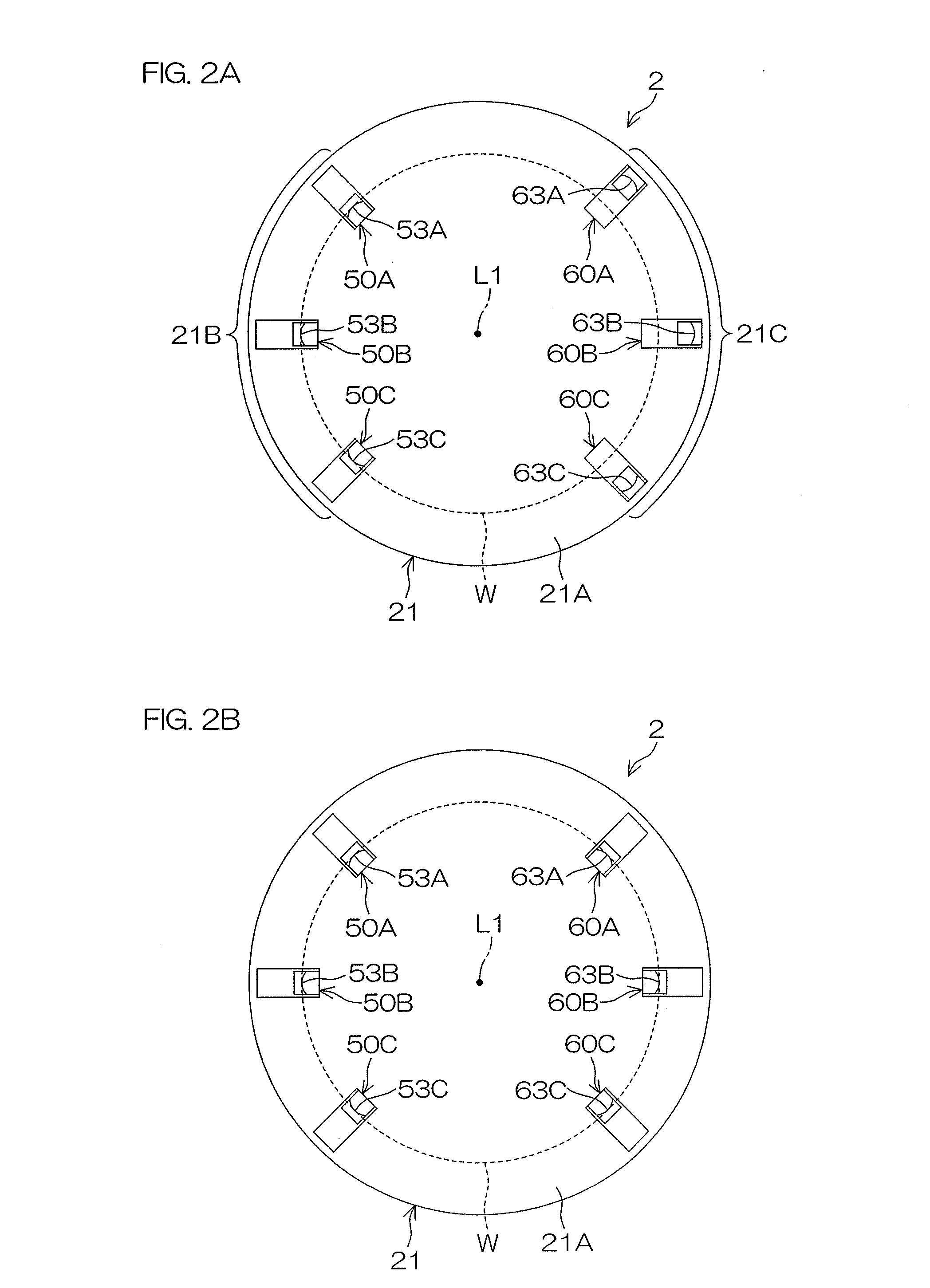
A substrate holding method is to horizontally hold a substrate, and includes a positioning step of positioning a substrate by moving a substrate transfer mechanism and by allowing the peripheral edge of the substrate to come into contact with the plurality of positioning pins, a substrate grasping step of bringing the plurality of grasping pins into a closed state after completing the positioning step so that the substrate held by the plurality of positioning pins and the plurality of grasping pins, and a transfer mechanism receding step of allowing the substrate transfer mechanism to recede from above the spin base after completing the substrate grasping step.

Description

BACKGROUND OF THE INVENTION[0001]1. Field of the Invention[0002]The present invention relates to a method for allowing a substrate holding / rotating device that has a spin base to hold a substrate, and relates to a substrate processing apparatus that includes this substrate holding / rotating device and a substrate transfer mechanism. Examples of substrates to be processed include semiconductor wafers, glass substrates for liquid crystal display devices, glass substrates for plasma displays, substrates for photomasks, substrates for optical disks, substrates for magnetic disks, substrates for magnet-optical disks, substrates for FEDs (Field Emission Displays), ceramic substrates, and substrates for solar cells.[0003]2. Description of Related Art[0004]A substrate processing apparatus that processes substrates, such as semiconductor wafers, is roughly divided into a batch type processing apparatus that processes a plurality of substrates in one operation and a single substrate processing...

Claims


Application Information

Patent Timeline
Patent Type & Authority Applications(United States)
IPC IPC(8): H01L21/687H01L21/68H01L21/677
CPCH01L21/68785H01L21/68H01L21/67742H01L21/68735H01L21/67051H01L21/67748H01L21/68728
Inventor KOBAYASHI, KAZUTAKAKATO, HIROSHI
Owner DAINIPPON SCREEN MTG CO LTD
Learn More