Object, Such as a Building, Provided with a System for Preventing Damage from Earthquakes to the Object

a technology for preventing earthquake damage and objects, applied in the field of objects, can solve the problems of increasing the distance the most destructive type of seismic wave, and the inability to detect the high frequency of the first wave at a greater distance, so as to prevent people's injuries and structural damage, and eliminate earthquake damage

Inactive Publication Date: 2016-10-06
ZOHAR OSHRI EVEN
View PDF2 Cites 8 Cited by
  • Summary
  • Abstract
  • Description
  • Claims
  • Application Information

AI Technical Summary

Benefits of technology

[0003]The present invention is directed towards assisting in the elimination of earthquake damage caused to objects, buildings and structures and the prevention of people's injuries and structural damage caused by seismic events or other event causing vibrations in the earth's surface.
[0004]While the definition of “objects” pertain mainly to buildings and architectural constructions, it may also comprise without limitation, to sensitive machinery, engineering constructions and the like.
[0005]Earthquake shaking and damage are the result of many different types of elastic waves. Among the many types of seismic waves, one can make a broad distinction between body waves and surface waves. While body waves travel through the interior of the earth, surface waves travel across the surface. Surface waves decay more slowly with distance than body waves. Surface waves tend to cause more damage.
[0006]Body waves travel through the interior of the earth. They create refractions due to varying density and stiffness of the earth's interior. The main types of body waves are referred to as primary (P) waves and secondary (S) waves.
[0007]P-waves are compressional waves that are longitudinal in nature. P waves are pressure waves that travel faster than other waves through the earth to arrive at seismograph stations first, hence the name “primary”. These waves can travel through any type of material, including fluids, and can travel at nearly twice the speed of S waves. In air, they take the form of sound waves, hence they travel at the speed of sound. Typical speeds are 300 m / s in air, 1450 m / s in water and about 5000 m / s in rock.
[0008]S-waves are shear waves that are transverse in nature. Following an earthquake event, S-waves arrive at seismograph stations after the faster-moving P-waves and displace the ground perpendicular to the direction of propagation. Depending on the propagation direction, the wave can take on different surface characteristics; for example, in the case of horizontally polarized S waves, the ground moves alternately to one side and then the other. S-waves can travel only through solids, as fluids (liquids and gases) do not support shear stresses. S-waves are slower than P-waves, and speeds are typically around 60% of that of P-waves in any given material.

Problems solved by technology

Surface waves tend to cause more damage.
Because of the long duration and large amplitude of the surface waves, they can be the most destructive type of seismic wave.
An earthquake occurs, seismographs near the epicenter are able to record both P and S waves, but those at a greater distance no longer detect the high frequencies of the first S wave.
However, the maximum tremor magnitude of shaking is unpredictable.
Also this method is quite expensive and is not necessarily suitable for all types of objects.
However, the device disclosed is not designed to move horizontally in an acceleration-resisting manner.
While this is an active device, it is not capable of inversing the ground movement within a real-time feedback loop that includes also the continuous monitoring of the payload center of mass and center of pressure.

Method used


Image

  • Object, Such as a Building, Provided with a System for Preventing Damage from Earthquakes to the Object
  • Object, Such as a Building, Provided with a System for Preventing Damage from Earthquakes to the Object
  • Object, Such as a Building, Provided with a System for Preventing Damage from Earthquakes to the Object

Examples


Embodiment Construction

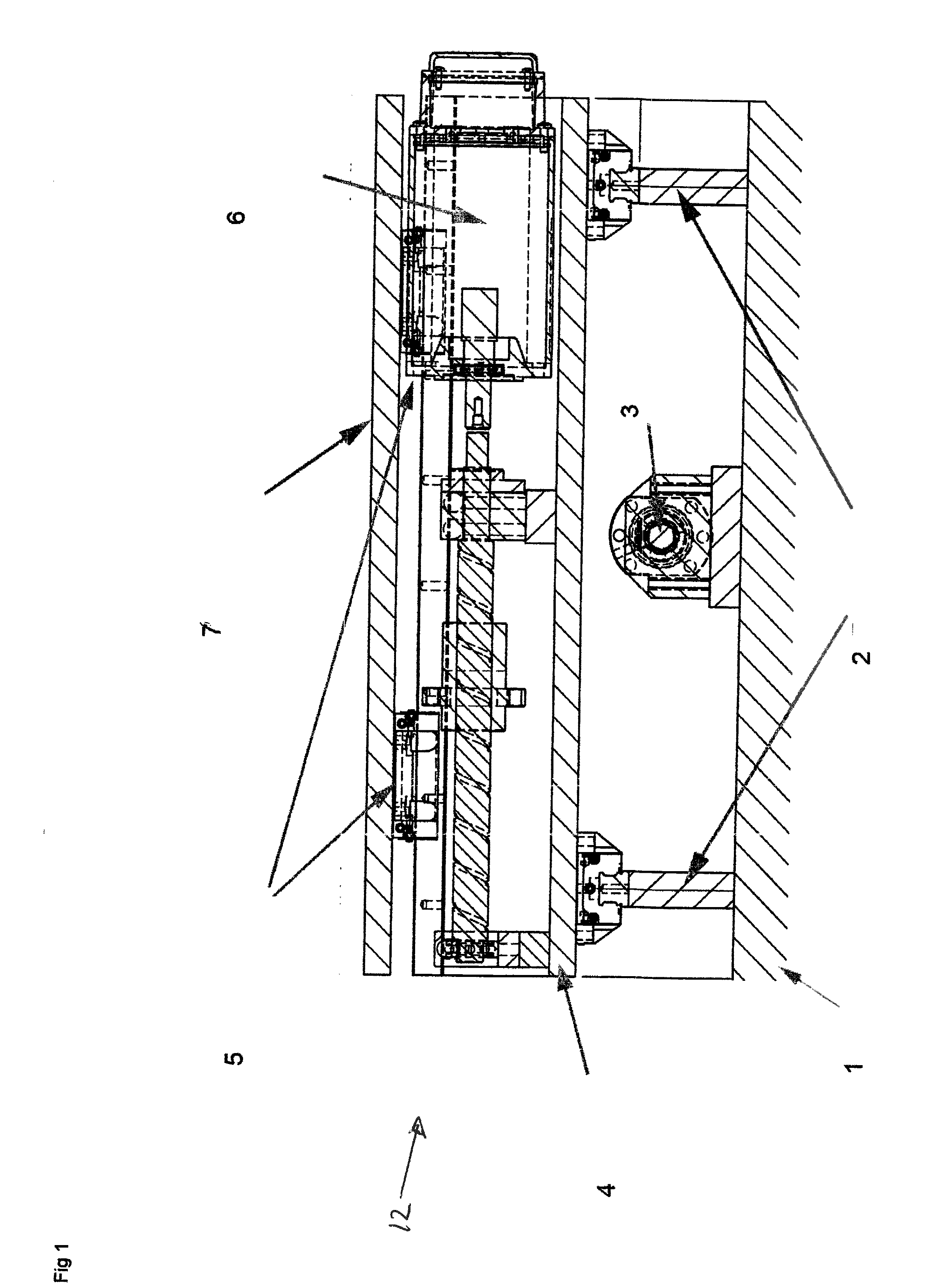
[0049]In a preferred embodiment, the system is comprised of an active foundation capable of two DoFs (Degrees of Freedom) and it can support also building superstructures.

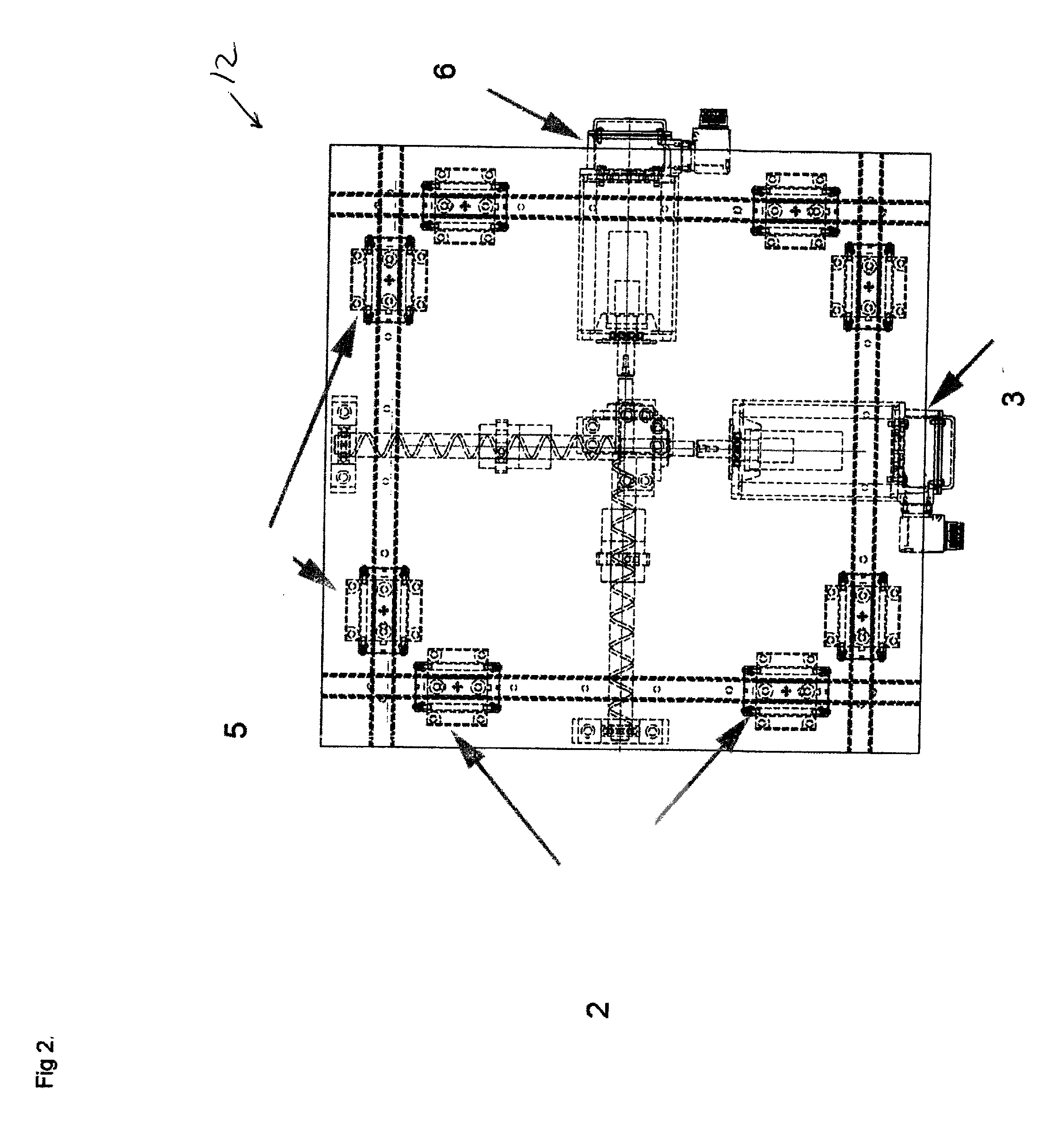
[0050]In FIG. 1 a side view of the assembled active foundation 12 is drawn. The Ground anchored foundation 1 is a large embedded concrete structure that also includes two protruding rails / guides 2. On it are also mounted the motors and / or actuators 3 that are driving the single Dof moving plate 4 responsible for real time inversion of a single axis component of the lateral seismic ground motion. The single Dof moving plate 4 also has two protruding rails / guides, rotated 90 degrees compared to the rails / guides of the ground anchored foundation. Mounted on the single Dof moving plate 4 are also motors and / or actuators 6 that are driving the second Dof moving plate 5. The top plate 7 with payload 11 is moved in real time to inverse the second single axis component of the lateral seismic ground motion.

[0051]FIG. 2 show...


PUM


Abstract

An object, such as a building, provided with a system for preventing damage from earthquakes to the object, said system comprising:
    • a foundation anchored to the ground;
    • guide means mounted on said foundation and on said object arranged to allow relative displacement between the object and the foundation in at least one horizontal direction;
    • at least one actuator arranged to displace said object in said at least one direction relative to said foundation;
    • said at least one actuator being connected to a central processing unit;
said central processing unit being connected to at least one displacement sensor;
said at least one displacement sensor being arranged to detect in real time displacement of said foundation and/or the ground and/or said object and to input in real time data about said displacement to said central processing unit; and
said processing unit being programmed to activate in real time said actuator in dependence on said data in such a manner that said object is displaced relative to said foundation in real time, such that the maximum displacement vector of the object relative to the earth's gravitational field is kept substantially smaller than the maximum displacement vector of said foundation relative to the earth's gravitational field.

Description

FIELD OF THE INVENTION[0001]The invention relates to an object, such as a building, provided with a system for preventing damage from earthquakes to the object.[0002]Disclosed here are methods and systems for eliminating the motions of objects that are caused by earthquakes. The present invention has the advantage of totally separating (rather than damping) the object's motions from the ground (earth) motions, keeping it fully motionless. Another advantage of the present invention is having minimal numbers of moving parts. In the described preferred embodiments, the methods of fully isolating sensitive objects from seismic waves are drawn.[0003]The present invention is directed towards assisting in the elimination of earthquake damage caused to objects, buildings and structures and the prevention of people's injuries and structural damage caused by seismic events or other event causing vibrations in the earth's surface.[0004]While the definition of “objects” pertain mainly to buildi...

Claims


Application Information

Patent Timeline
Patent Type & Authority Applications(United States)
IPC IPC(8): E04B1/98H04N5/232G05B13/02G01V1/00E04H9/02E02D27/34
CPCE04B1/985E04H9/021H04N5/232G05B13/021G01V1/008E02D27/34E04H9/0235H04N23/635E04H9/0215
Inventor ZOHAR, OSHRI EVEN
Owner ZOHAR OSHRI EVEN
Why Eureka
Try Eureka