
Receiver and fbmc reception method with low decoding latency

Active Publication Date: 2016-10-13
COMMISSARIAT A LENERGIE ATOMIQUE ET AUX ENERGIES ALTERNATIVES
View PDF4 Cites 6 Cited by
  • Summary
  • Abstract
  • Description
  • Claims
  • Application Information

AI Technical Summary

Benefits of technology

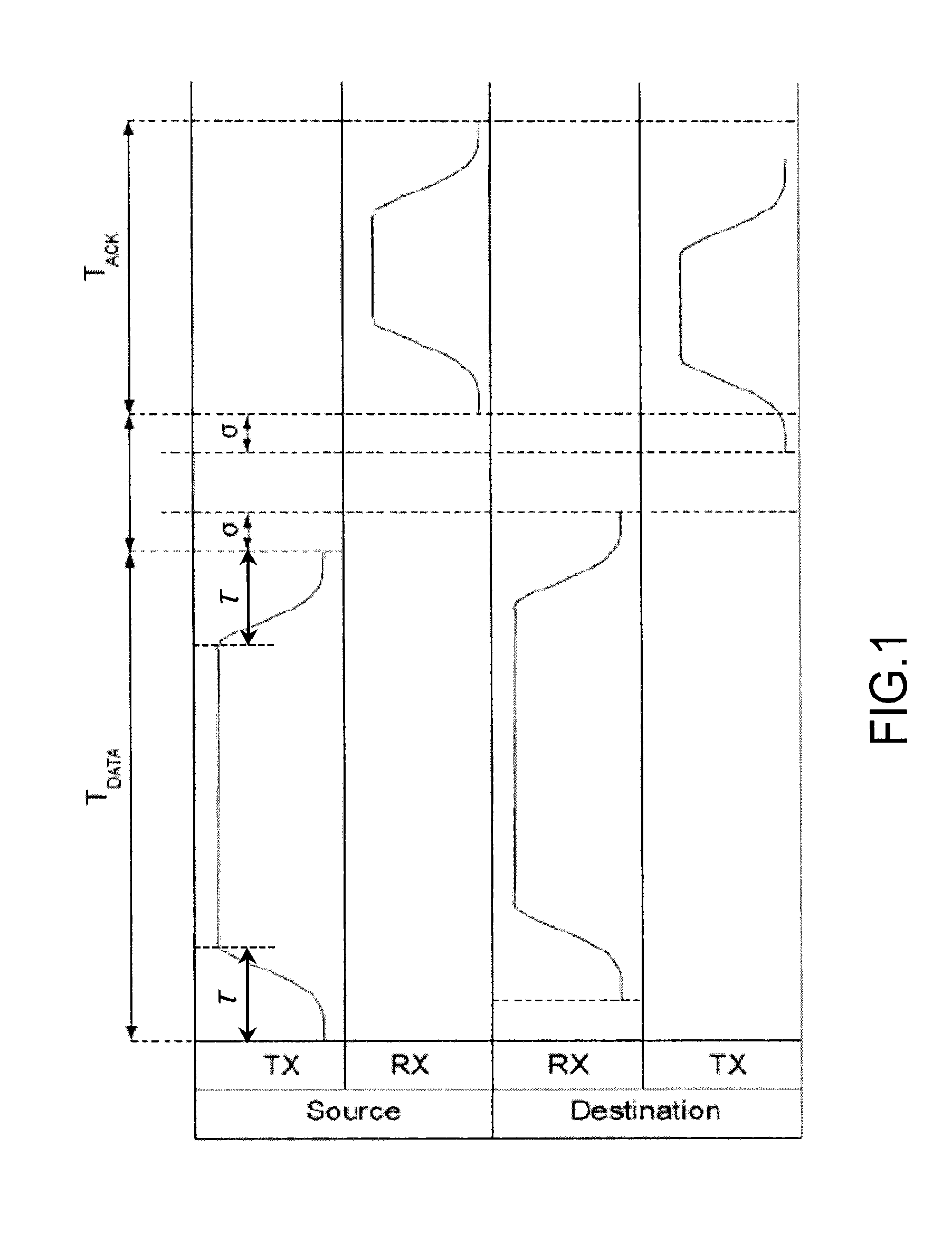
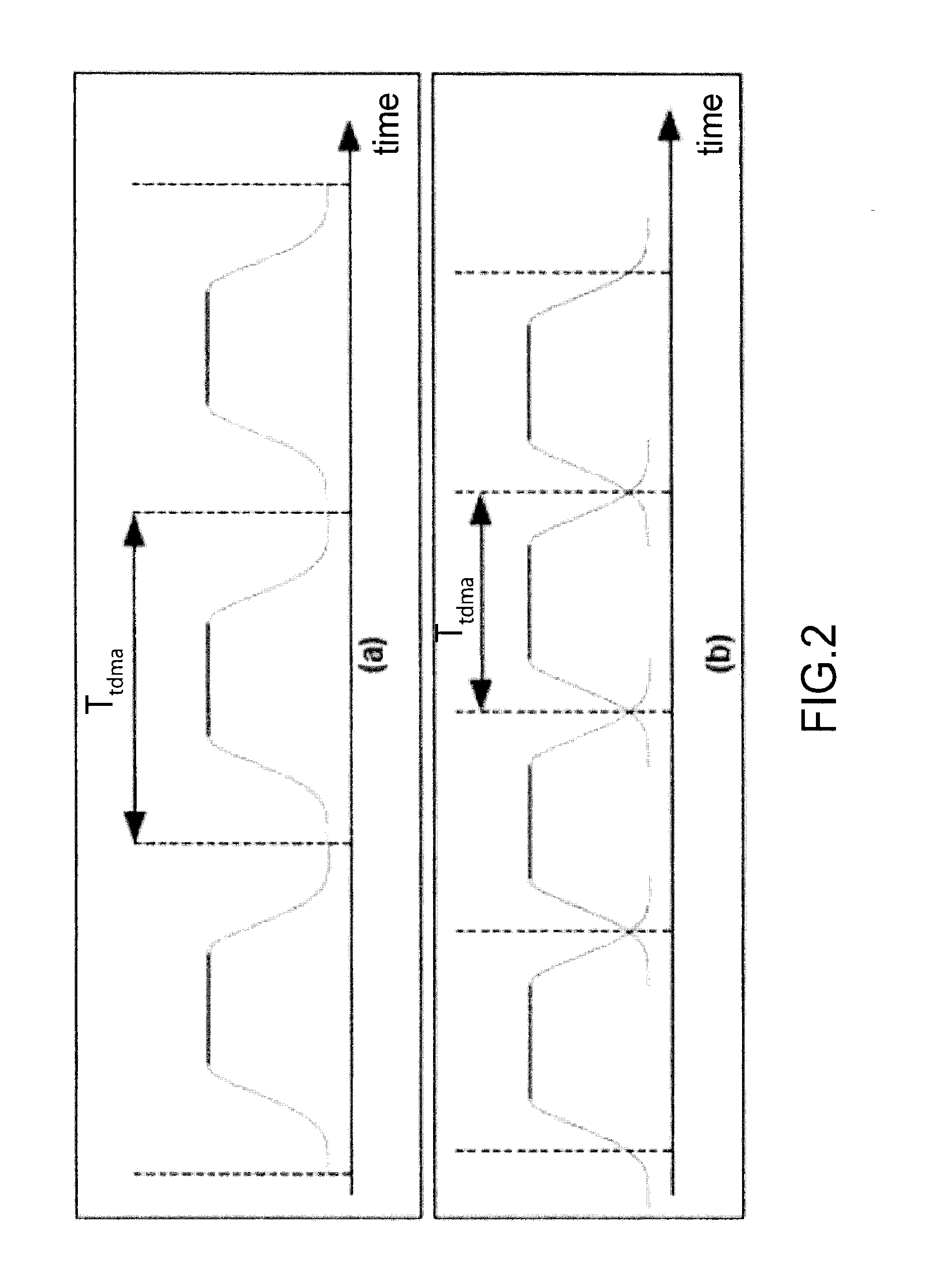
The present invention relates to telecommunication systems using multi-carrier modulation, specifically filter bank multi-carrier (FBMC) modulation. The technical effect of this invention is to provide a better solution for applications requiring high out-of-band rejection rates, as compared to OFDM modulation. The FBMC modulation offers good frequency localization of the signal, but the time spread of the FBMC symbols can negatively impact the data rate, especially in communication protocols such as the handshake protocol or the TDMA protocol. The invention proposes a solution to mitigate the impact of time spread on the data rate.

Problems solved by technology

In fact, since the time localisation of the signal is very good (the signal is delimited by a time slot), the frequency localisation is not good (sinc function secondary lobes spreading out-of-band).
Consequently OFDM modulation is not an optimal solution for applications requiring high out-of-band rejection rates.
Conversely, when the packets of FBMC symbols are of small size, notably when the payload of the signal is low with regard to that of the preamble, the time spread may become very penalising in terms of rate.
When the different users transmit their packets by means of a FBMC modulation, the time occupancy of the transmission intervals is not optimal.

Method used


Image

  • Receiver and fbmc reception method with low decoding latency
  • Receiver and fbmc reception method with low decoding latency
  • Receiver and fbmc reception method with low decoding latency

Examples


first embodiment

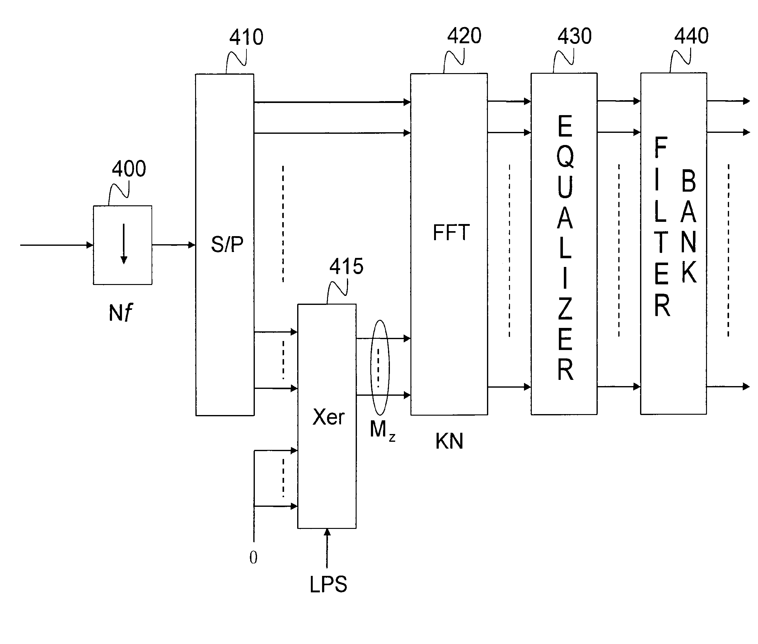
[0034]FIG. 4 schematically represents the architecture of a FBMC receiver according to the invention;

[0035]FIG. 5 represents the principle of zero padding of the samples of the last FBMC symbol of a packet received by the receiver of FIG. 4;

[0036]FIG. 6 represents the change in the signal to interference ratio at the level of the receiver as a function of the zero padding rate;

[0037]FIGS. 7A and 7B represents the variation in the rate in saturated mode as a function of the number of users for two separate sizes of packets;

second embodiment

[0038]FIG. 8 schematically represents the architecture of an FBMC receiver according to the invention.

DETAILED DESCRIPTION OF PARTICULAR EMBODIMENTS

[0039]The basic idea of the present invention is not to window the FBMC signal at the level of the transmitter and in particular not to truncate the impulse response of the prototype filter but on the contrary to carry out a treatment at the level of the receiver while padding the last samples of the last block received with zeros before carrying out the FFT. It has in fact been able to be shown that it is possible to only use a partial information to decode the last FBMC symbols. FIG. 4 schematically represents the structure of an FBMC receiver according to a first embodiment of the invention.

[0040]The FBMC signal received, after having been demodulated in baseband, is sampled by a sampler, 400, at the frequency Nf where f=1 / T, is the symbol frequency. The successive samples are grouped together, by a serial / parallel converter, 410, in ...


PUM


Abstract

The invention relates to a receiver and a FBMC reception method making it possible to reduce the decoding latency time and to increase the data rate in a communication system using a handshake exchange protocol or a TDMA access protocol. The receiver introduces zero padding values in place of the last samples of the last block of samples of a FBMC packet, without waiting for the end of this packet. The decoding of the FBMC packet is thus decoded more rapidly, without significant degradation of the error rate and without reduction of the out-of-band rejection rate of the FBMC signal.

Description

TECHNICAL FIELD[0001]The present invention relates, generally speaking, to the field of telecommunication systems using filter bank multi-carrier modulation, also designated FBMC (Filter Bank Multi-Carrier) systems.STATE OF THE PRIOR ART[0002]Telecommunication systems using multi-carrier modulation are well known in the prior art. The principle of such modulation consists in dividing the transmission band into a plurality of frequency sub-channels associated with sub-carriers and modulating each of these sub-carriers by the data to transmit.[0003]The most widespread multi-carrier modulation is without any doubt OFDM (Orthogonal Frequency Division Multiplexing) modulation. This is implemented in wireless local area networks (WLAN), WiFi, wireless broadband internet access (WiMAX), digital broadcasting systems (DVB-T, ISDB-T, DAB), asymmetric digital subscriber lines (xDSL), fourth generation cellular telephony (LTE), etc.[0004]The spectral occupation of an OFDM signal is nevertheless...

Claims


Application Information

Patent Timeline
IPC IPC(8): H04L27/26H04B1/16
CPCH04B1/16H04L27/265H04L27/2654
Inventor DORE, JEAN-BAPTISTE
Owner COMMISSARIAT A LENERGIE ATOMIQUE ET AUX ENERGIES ALTERNATIVES
Learn More