Pump for discharging contents

a technology for discharging contents and pumps, which is applied in the direction of positive displacement liquid engines, packaging foodstuffs, packaged goods types, etc., can solve the problems of corroding metal balls and metallic springs, difficult to separate synthetic resins and metallic materials from each other, and polluted contents, so as to achieve high market competitiveness, reduce product costs, and minimize the number of components

Active Publication Date: 2016-10-20
KANG SUNGIL
View PDF7 Cites 5 Cited by
  • Summary
  • Abstract
  • Description
  • Claims
  • Application Information

AI Technical Summary

Benefits of technology

[0032]According to the present invention, the pump inner body serves as a pump cylinder as well as a suction valve and a dispensing valve, so the number of components can be minimized, so that the assembling productivity can be improved and the product cost can be reduced, thereby providing the pump for discharging contents having the high market competitiveness.
[0033]In addition, according to the present invention, the pump operation is performed by changing a volume of the contents temporary reservoir by folding and unfolding the inner body barrel of the pump inner body, so the pump has a short working stroke distance, so that the pump can be easily applied to a product such as a compact having a short height.
[0034]Further, the present invention can provide the pump for discharging contents, in which components making contact with the contents, such as a suction valve or a dispensing valve, are formed of materials durable against the chemical composition instead of metallic materials to prevent corrosion caused by the contents, thereby extending the product life cycle and preventing the contents from being spoiled caused by chemical reaction between the contents and the components.

Problems solved by technology

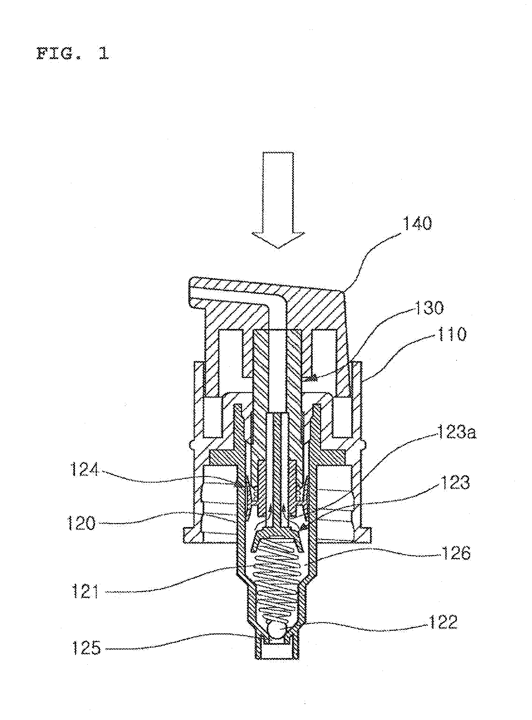
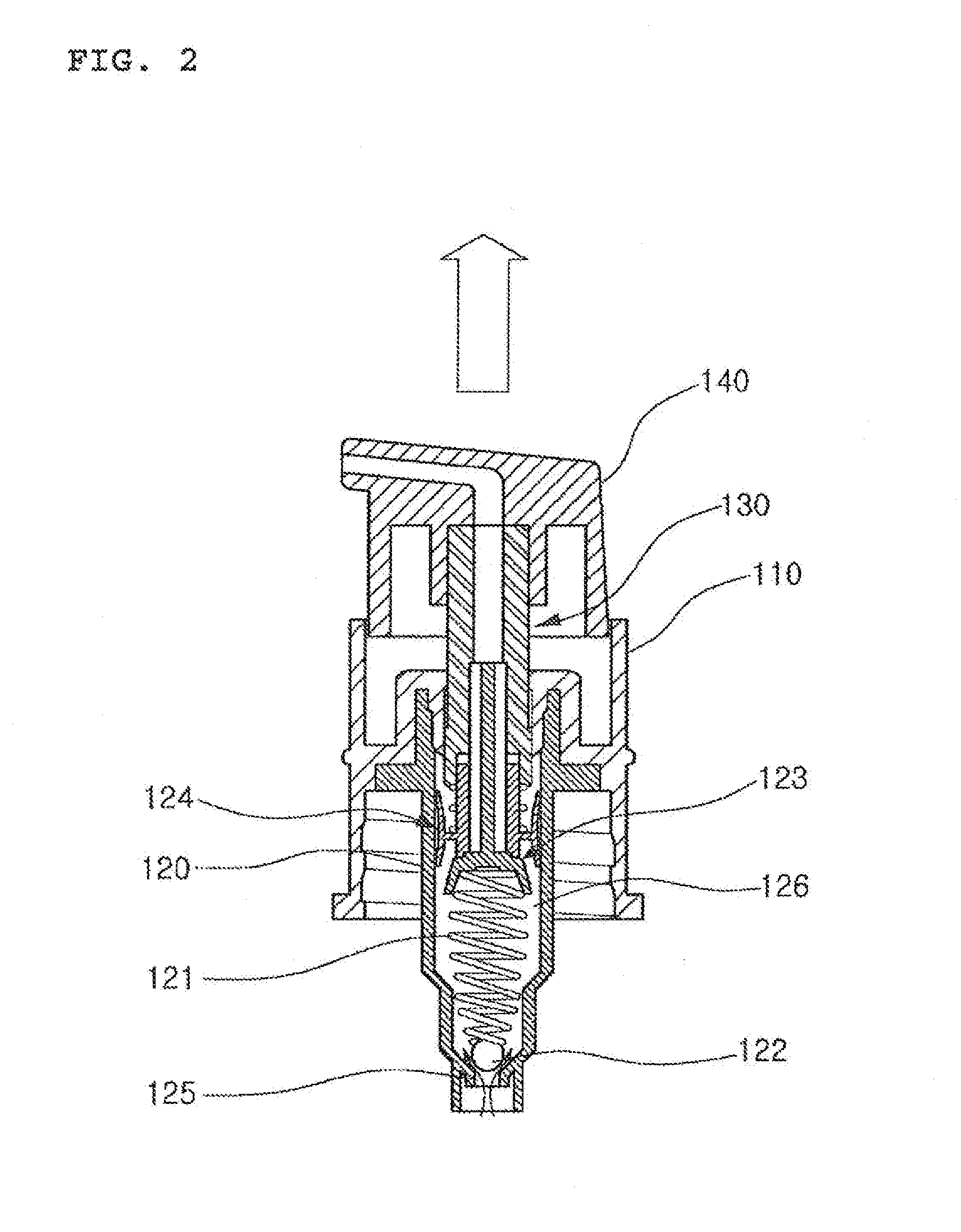
However, the contents dispensing pump has a major drawback that, since a metallic ball and metallic spring are used as the opening and closing means for dispensing contents, the metallic ball and metallic spring are corroded due to chemical reaction with the contents so that the contents are polluted.
In addition, since synthetic resin and metal are used as materials of the contents dispensing pump, when the used contents dispensing pump is discarded, it is difficult to separate the synthetic resin and metallic materials from each other, so that it is difficult to perform resource recycling.
Further, the structure of the contents dispensing pump according to the related art is complex, so that the productivity is deteriorated and the product price is increased.
Specifically, since the dispensing pump structurally has a long working stroke distance, when the dispensing pump is applied to a product such as a compact having a height smaller than a width, it is difficult to mount the dispensing pump on the product due to a small mounting space.

Method used


Image

  • Pump for discharging contents
  • Pump for discharging contents
  • Pump for discharging contents

Examples


Embodiment Construction

[0055]It should be understood that the terms used in the specification and the appended claims should not be construed as limited to general and dictionary meanings, but interpreted based on the meanings and concepts corresponding to technical aspects of the present invention on the basis of the principle that the inventor is allowed to define terms appropriately for the best explanation.

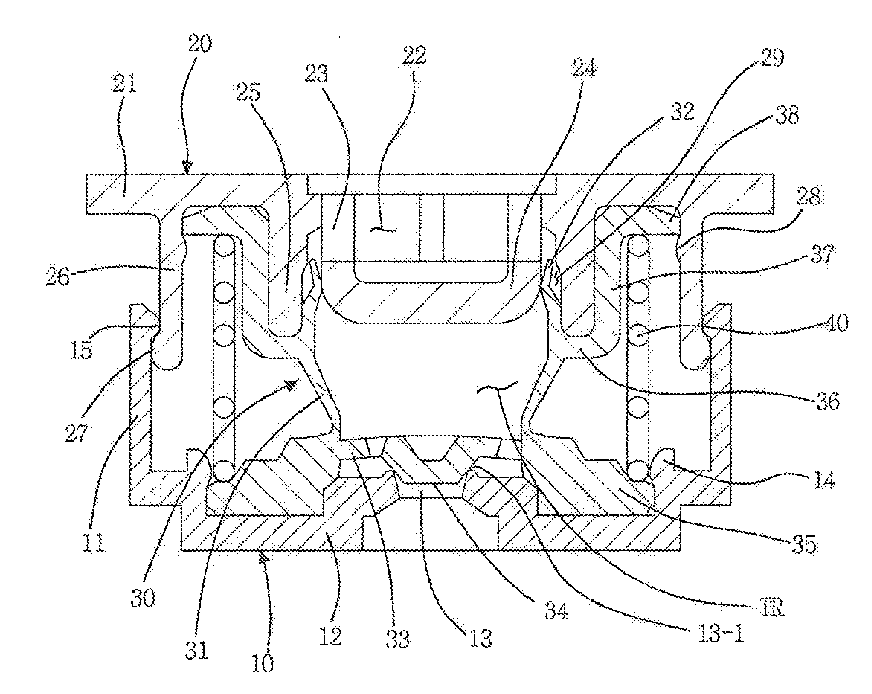
[0056]FIG. 6 is an assembled perspective view of a pump for discharging contents according to one embodiment of the present invention, FIG. 7 is an exploded perspective view of a pump for discharging contents according to one embodiment of the present invention, and FIG. 8 is an assembled sectional view of a pump for discharging contents according to one embodiment of the present invention. In addition, FIG. 9 is a perspective view of a pump inner body applied to the present invention and FIG. 10 is a bottom perspective view of a pump inner body applied to the present invention.

[0057]Hereinafter an ...


PUM


Abstract

The present invention relates to a pump for discharging contents, in which a pump upper body having contents outlets formed therein is inserted into the upper part of a pump main body having a contents inlet formed therein, a pump inner body is fitted into the inside of the pump main body and the pump upper body, the pump inner body integrally includes the serving as a temporary content reservoir for temporarily storing the contents, a suction valve plate for sucking the contents, and a discharge valve protruding ring for discharging the contents, and thus the contents are discharged as the volume of the temporary content reservoir in the pump inner body is changed by vertically moving the pump upper body relative to the pump main body.

Description

CROSS-REFERENCE TO RELATED APPLICATION[0001]This application claims the benefit of Korean Application No. 10-2013-0137515, filed on Nov. 13, 2013 with the Korean Intellectual Property Office, the disclosure of which is incorporated herein by reference.TECHNICAL FIELD[0002]The present invention relates to a pump for discharging contents, which is mounted on a container containing the contents and is used to allow a user to discharge the contents from the container by a predetermined amount at a time by a pumping operation and to use the discharged contents. More particularly, the present invention relates to a pump for discharging contents, in which a pump upper body having contents outlets formed therein is inserted into the upper part of a pump main body having a contents inlet formed therein, a pump inner body is fitted into the inside of the pump main body and the pump upper body, the pump inner body integrally includes an inner body barrel serving as a temporary content reservoi...

Claims


Application Information

Patent Timeline
Patent Type & Authority Applications(United States)
IPC IPC(8): B05B11/00F04B19/22F04B53/14A45D34/00
CPCB05B11/3025A45D34/00A45D2200/056F04B53/14F04B19/22A45D33/025B05B11/1025B05B11/028B05B11/1033B05B11/1074B65D47/00B65D83/00B05B11/00
Inventor KANG, SUNGIL
Owner KANG SUNGIL
Why Eureka
Try Eureka