Contents dispensing pump

a technology of content and dispensing pump, which is applied in the direction of packaging, single-unit apparatus, closures, etc., can solve the problems of corroding metal bail and metallic spring, difficult to separate synthetic resin and metallic materials from each other, and polluted contents, etc., to improve reliability, simple structure, and easy manufacturing

Active Publication Date: 2016-10-20
KANG SUNGIL
View PDF7 Cites 11 Cited by
  • Summary
  • Abstract
  • Description
  • Claims
  • Application Information

AI Technical Summary

Benefits of technology

[0037]According to the present invention, there is provided the contents dispensing pump including a pump main body aid a pump upper body which are separated from each other and formed of a hard material, where an pump inner body is coupled to insides of the pump main body and the pump upper body, so that, when contents are dispensed by changing a volume of the content temporary reservoir while the pump upper body moves up or down, with respect to the pump main body, the volume of the content temporary reservoir is changed by deforming the pump inner body. Thus, the components are prevented from being worn due to the friction between the pump main body and the pump upper body so that the product defective is prevented, thereby improving the reliability.
[0038]In addition, according to the present invention, there is provided a pump for discharging contents, which has a simple structure to be easily manufactured so that the productivity is improved and the product price is reduced.
[0039]Specifically, according to the present invention, the contents dispensing pump including the pump inner body and the dispensing valve separated from each, other are formed of mutually different materials to prevent the pump inner body from being billowed before the dispensing valve is operated, so that a constant amount of contents can be dispensed ail the time.
[0040]In addition, According to the present invention, the components constituting the contents dispensing pump are formed of an elastic material such as rubber or synthetic resin durable to a chemical material, so that the opening and closing means may be prevented from being corroded due to the contents, and a metallic material is not used for valve means in the contents dispensing pump so that the used content discharging pump may be recycled.
[0041]In addition, the contents dispensing pump has a short working stroke distance so that the contents dispensing pump may be easily applied to a product such as a compact having a height less than a width thereof.

Problems solved by technology

However, the contents dispensing pump has a major drawback that, since a metallic bail and metallic spring are used as the opening and closing means for dispensing contents, the metallic bail and metallic spring are corroded due to chemical reaction with the contents so that the contents are polluted.
In addition, since synthetic resin and metal are used as materials of the contents dispensing pump, when the used contents dispensing pump is discarded, it is difficult to separate the synthetic resin and metallic materials from each other, so that it is difficult to perform resource recycling.
Specifically, the structure of the contents dispensing pump according to the related art is complex, so that the productivity is deteriorated and the product price is increased.
In addition, since the dispensing pump structurally has a long working stroke distance, when the dispensing pump is applied to a product such as a compact haying a height less than a width thereof, it is difficult to mounting the dispensing pump on the product due to a small mounting space.
Thus, according to the dispensing pump, the pump main body 310 serves as a cylinder and the pump upper body 320 serves as a piston, the friction between the pump main body 310 and the pump upper body 320 is increased so that the dispensing pump is not smoothly operated and large force is required to operating the dispensing pump, so it is inconvenient to operate the dispensing pump.
In addition, due to the friction between the pump main body 310 and the pump tipper body 320, the abrasion becomes severe so that an abnormal phenomenon may occur in use.

Method used


Image

  • Contents dispensing pump
  • Contents dispensing pump
  • Contents dispensing pump

Examples


Embodiment Construction

[0063]It should be understood that the terms used in the specification and the appended claims should not be construed as limited to general and dictionary meanings, but interpreted based on the meanings and concepts corresponding to technical aspects of the present invention on the basis of the principle that the inventor is allowed to define terms appropriately for the best explanation.

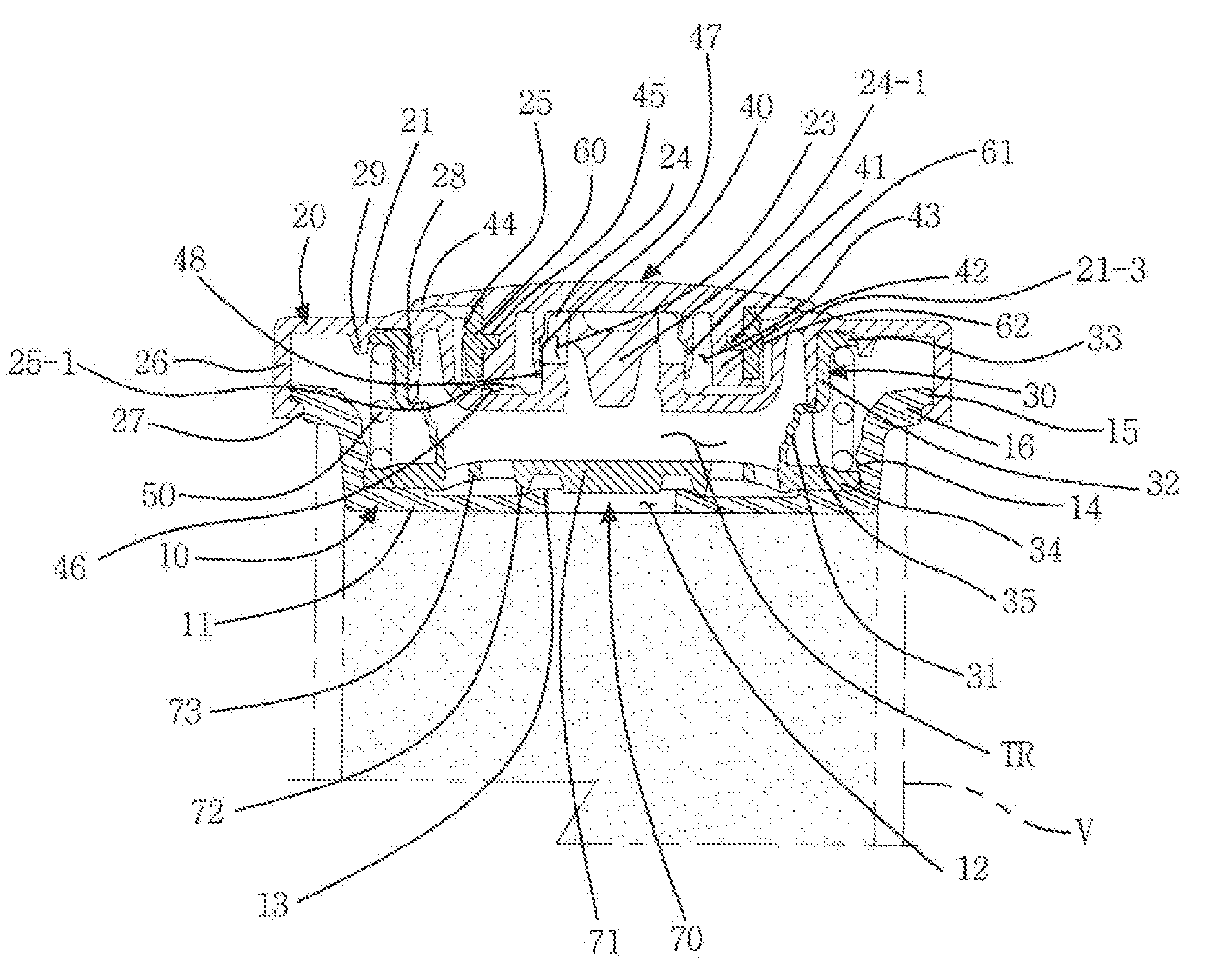
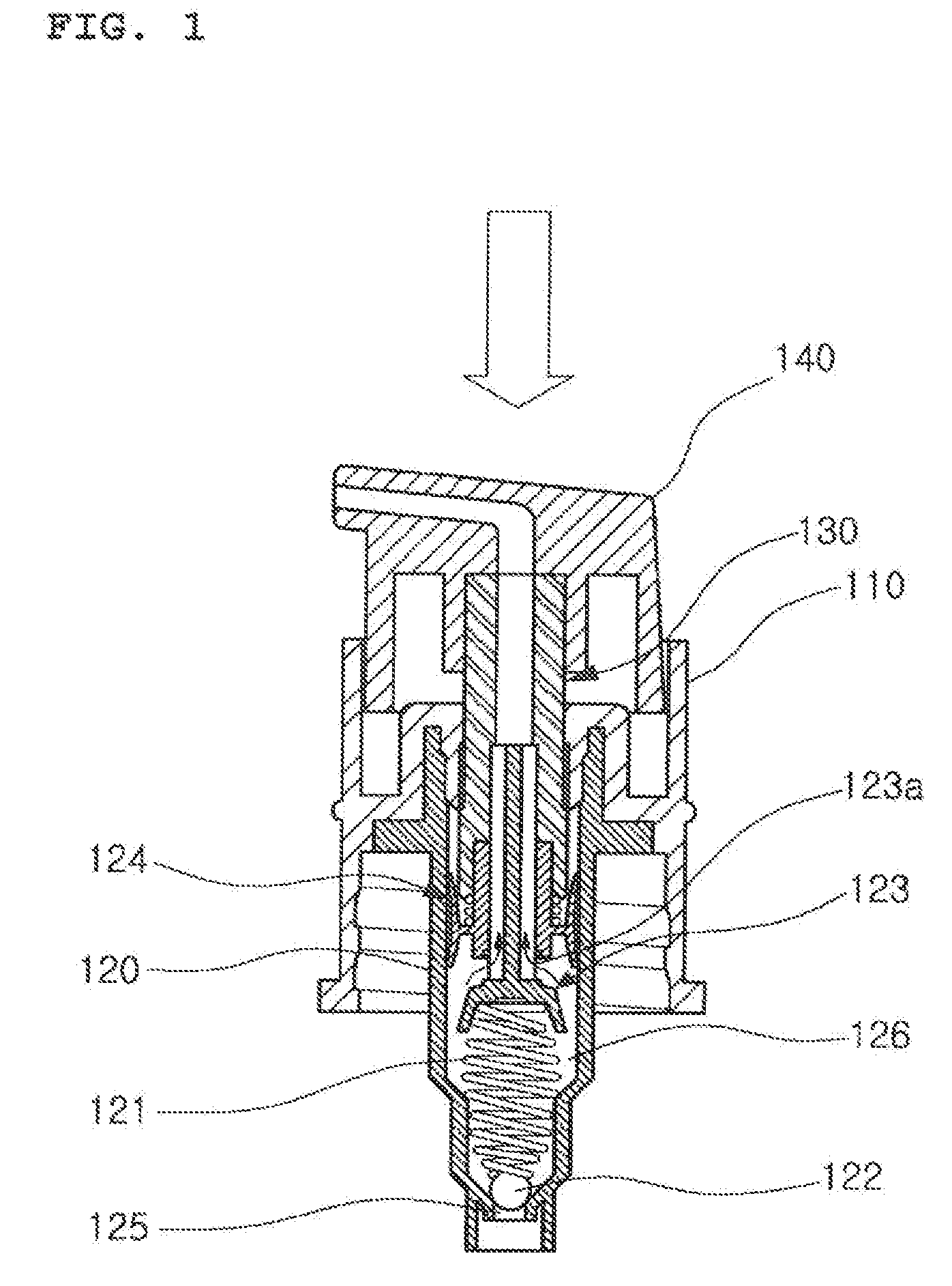
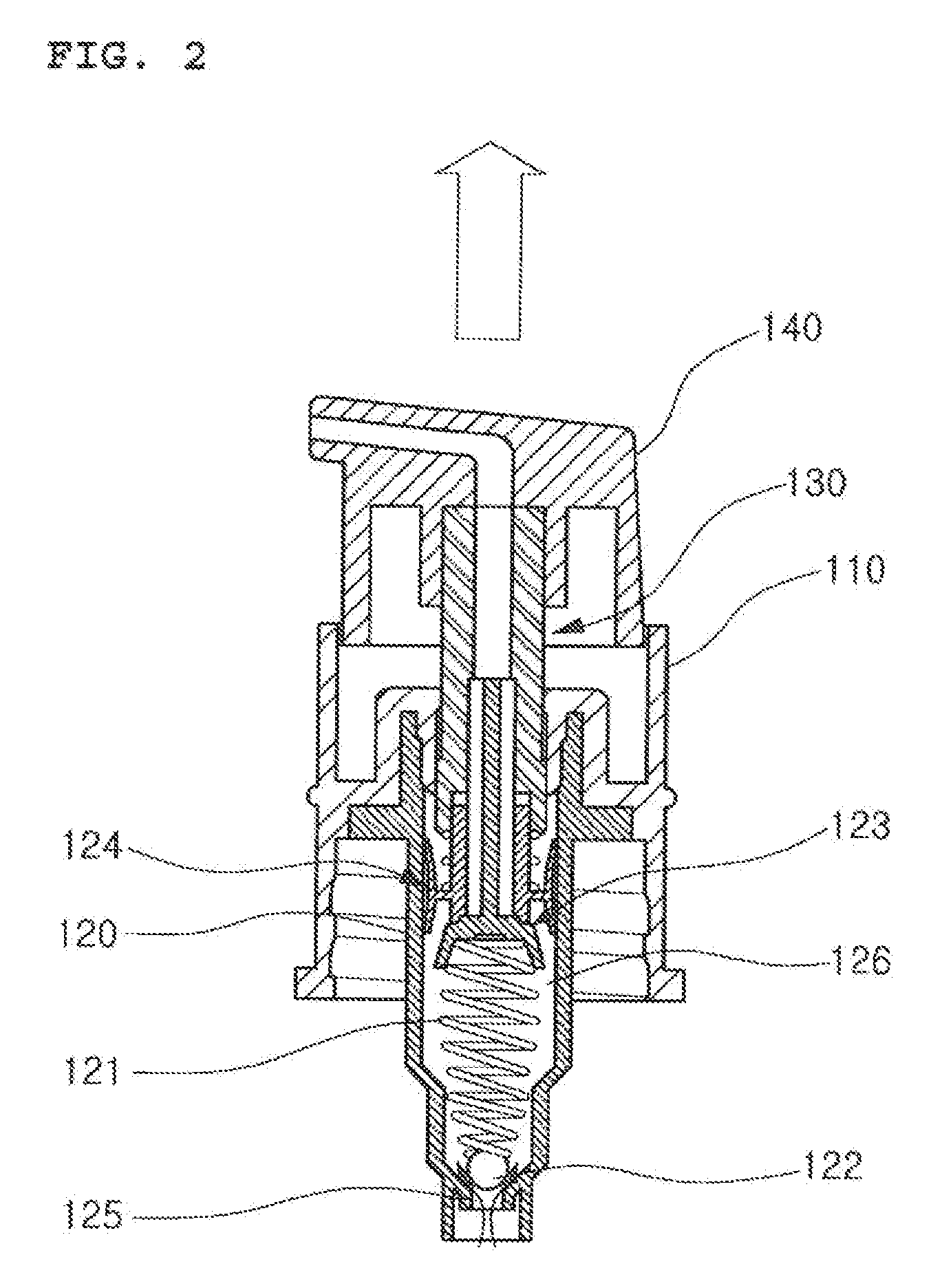
[0064]FIG. 9 is an assembled perspective view of a contents dispensing pump according to still another example of the related art. FIG. 10 is an exploded perspective view of a contents dispensing pump according to an embodiment of the present invention. FIG. 11 is an assembled sectional view of a contents dispensing pump according to an embodiment of the present invention. FIG. 12 is a plan view of a pump inner body applied to the present invention. FIG. 13 is a sectional view taken along line A-A′. FIGS. 14 to 17 are plan views showing other examples of the pump inner body applied to the present in...


PUM


Abstract

The present invention relates to a contents dispensing pump which is coupled to a container (V) for accommodating the contents therein and dispenses the contents, comprising; a pump main body (10); a pump upper body (20); a pump inner body (30); a dispensing valve (40); and an elastic member (50). The pump upper body (20) is coupled to the upper side of the pump main body (10) so that a pumping operation is made by an up and down movement with respect to the pump main body (10). The pump inner body (30) has a bowl shape with the middle thereof formed to be dented so that an inlet valve plate (70) is integrally formed on the lower surface. The dispensing valve (40) is coupled to the upward side of the pump upper body (20), and has, formed therein, a valve protrusion wheel (41) for opening and closing the content outlet (23). The elastic member (50) is positioned between the upper lateral surface extension piece (33) and the lower lateral surface extension piece (34) of the pump inner body (30) so as to draw the pump inner body (30) and simultaneously elastically support the pump main body (10) and the pump upper body (20).

Description

CROSS-REFERENCE TO RELATED APPLICATION[0001]This application claims the benefit of Korean Application No. 10-2013-0137515, filed on Nov. 13, 2013 with the Korean Intellectual Property Office, the disclosure of which is incorporated herein by reference.TECHNICAL FIELD[0002]The present invention relates to a contents dispensing pump which is mounted on a container so as to dispense, to an outside, contents contained in the container by a fixed quantity through a pumping operation and use the contents, and more particularly, to a contents dispensing pump which increases productivity and lowers the product price due to a simple structure of the contents dispensing pump configured in such a manner that a pump upper body is inserted onto the upper portion of a pump main body, a pump inner body is inserted on the inside of the pump upper body and the pump main body, a valve protrusion wheel of a dispensing valve is coupled to a dispensing protrusion rod of the upper portion of the pump upp...

Claims


Application Information

Patent Timeline
Patent Type & Authority Applications(United States)
IPC IPC(8): B05B11/00
CPCB05B11/3028B05B11/3046B05B11/3078B05B11/004B05B11/0032B05B11/007B05B11/0041B05B11/028B05B11/1025B05B11/1028B05B11/1069B05B11/1077B65D47/00B05B11/00B65D83/00
Inventor KANG, SUNGIL
Owner KANG SUNGIL
Why Eureka
Try Eureka