
Multi-Phase Flow Decomposition Using Electrical Capacitance Volume Tomography Sensors

a technology of electrical capacitance and tomography, which is applied in the field of multi-phase flow decomposition using electrical capacitance volume tomography sensors, can solve the problems of difficult to identify each phase concentration from a single capacitance measurement, and the number of physical properties cannot be inferred directly from the conventional capacitance imaging method

Active Publication Date: 2016-10-27
TECH4IMAGING
View PDF6 Cites 24 Cited by
  • Summary
  • Abstract
  • Description
  • Claims
  • Application Information

AI Technical Summary

Benefits of technology

The patent text describes a method for measuring the distribution of different phases in a multi-phase flow system using electrical capacitance sensors. The method is based on the principle of the Maxwell-Wagner-Sillars (MWS) polarization effect, which is a change in effective dielectric constant caused by the presence of a conductive phase. By measuring the capacitance signal at different frequencies, the method can identify each phase and measure its concentration separately. This allows for better control and optimization of multi-phase flow systems. The text also describes a technique called Electrical Capacitance Tomography (ECT) that uses multiple capacitance sensors to reconstruct the volume concentration or physical properties of each phase in the imaging domain. The relationship between effective dielectric constant and operating frequency is also discussed, along with different formulations that can be used to estimate the effective dielectric constant. The technical effect of the patent text is to provide a reliable and accurate method for measuring the distribution of different phases in a multi-phase flow system using electrical capacitance sensors.

Problems solved by technology

For three or more phases, it is difficult to identify each phase concentration from a single capacitance measurement.
Moreover, a number of physical properties can't be inferred directly from the conventional capacitance imaging method.

Method used


Image

  • Multi-Phase Flow Decomposition Using Electrical Capacitance Volume Tomography Sensors
  • Multi-Phase Flow Decomposition Using Electrical Capacitance Volume Tomography Sensors
  • Multi-Phase Flow Decomposition Using Electrical Capacitance Volume Tomography Sensors

Examples


Embodiment Construction

)

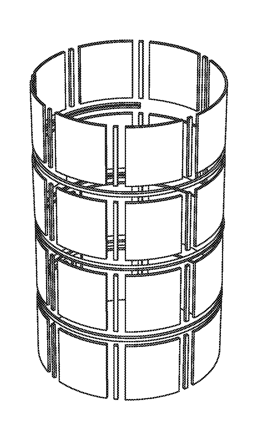
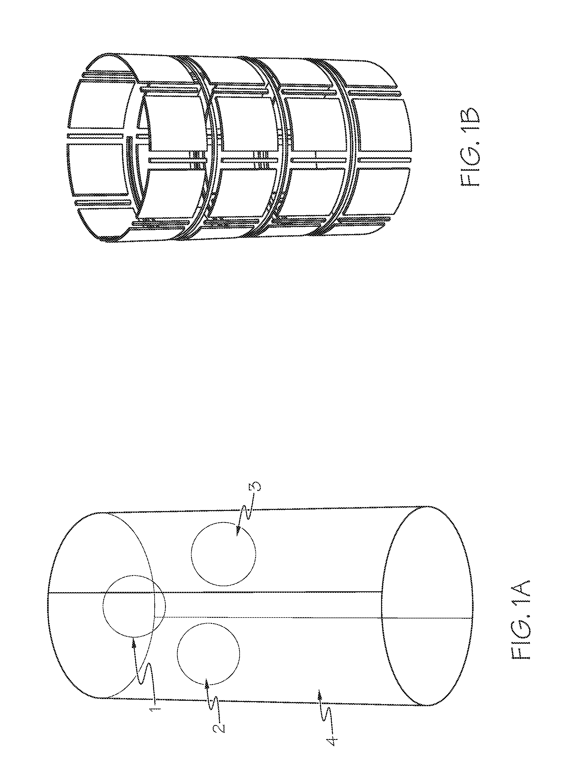
[0035]FIG. 1A illustrates one embodiment of three phases (1,2,3) each having different electrical properties, in a background of a continuous phase (4). FIG. 1B illustrates one embodiment of the sensor of the present invention. In one embodiment, the sensor is comprised of 24 plates. Each phase component will affect the effective dielectric constant of the mixture and introduce a frequency dependent response based on the electrical properties of the phases and the background.

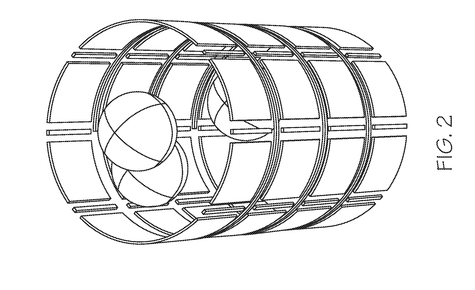
[0036]FIG. 2 illustrates the embodiment of the sensor of FIG. 1B with the phases inside. As the flow evolves, the multi-phase components move inside the sensor. Capacitance measurements between different plate combinations will also change in response to multiphase flow motion. A phase in the multiphase flow will also cause the capacitance to change as a function of frequency. This change is related to that phase concentration, volume fraction, and electrical properties.

[0037]FIG. 3 illustrates one embodiment a...


PUM


Abstract

The present invention provides a system and method for multi-phase flow decomposition using electrical capacitance imaging techniques. The present invention provides a system and method to obtain permittivity distributions at a plurality of frequency markers using volume tomography image reconstruction to determine volume fraction of each phase and to produce images of the volume fraction for each phase.

Description

CROSS-REFERENCE TO RELATED APPLICATIONS[0001]This application claims priority to U.S. Provisional Application No. 62 / 153,095 filed on Apr. 27, 2015, and is herein incorporated by reference in its entirety.BACKGROUND AND SUMMARY OF THE INVENTIVE FIELD[0002]Multi-phase flow systems are the interaction between materials in which each has distinct and homogenous physical properties. Each component in the flow that is homogenous in its physical properties and separable is referred to as Phase. In a flow system, phase measurement is important to properly optimize, control, and predict multiphase flow systems. Phase physical properties that are required to optimize of measure a multiphase process are phase distribution, velocity, and mass flow rate. It is desired to obtain such measurements for each phase individually while all phases are interacting in a multiphase flow system. For example, for a multiphase flow system consisting of gas, liquid, and solid particles, measured information o...

Claims


Application Information

Patent Timeline
IPC IPC(8): A61B5/053G01N27/22G01R27/26
CPCA61B5/0536A61B2562/0214G01N27/221G01R27/2623A61B5/004A61B5/02007A61B5/1076G01F1/708G01F1/74
Inventor MARASHDEH, QUSSAI
Owner TECH4IMAGING
Learn More