Heating plate, conductive pattern sheet, vehicle, and method of manufacturing heating plate

a technology of conductive pattern and heating plate, which is applied in the direction of vehicle maintenance, vehicle cleaning, transportation and packaging, etc., can solve the problems of difficult to make extremely thin heating wires, difficulty in exhibiting excellent see-through properties, and positioning operation requires time and effort in order to precisely. , to achieve the effect of restricting the bubbles from remaining in the heating pla

Active Publication Date: 2016-10-27
DAI NIPPON PRINTING CO LTD
View PDF3 Cites 23 Cited by
  • Summary
  • Abstract
  • Description
  • Claims
  • Application Information

AI Technical Summary

Benefits of technology

[0128]According to the fifth embodiment of the present invention, it is possible to restrain bubbles from remaining in a heating plate.

Problems solved by technology

Thus, in consideration of heat generation by the resistance heat of the electric wire upon being powered, it is difficult to make extremely thinner the heating wire.
Thus, when the heating wire as disclosed in JP9-207718A is used in the defroster apparatus, there is a difficulty in exhibiting an excellent see-through property, while realizing a suitable heat generation function.
However, this positioning operation requires time and effort in order to precisely position the electric wires.
However, in the case where the sidewall of a heating wire has a shape that extends along the normal direction of the sheet plane of the substrate or the overhang shape, when the heating wire and the joint layer are brought into contact with each other in the heating and pressurizing step during the manufacture of a heating plate, it is difficult for the joint layer to get into a root side of the heating wire, so that bubbles are likely to remain around the sidewall of the heating wire.
These bubbles may impair an appearance quality of the heating plate as well as resulting in glaring (glittering).

Method used


Image

  • Heating plate, conductive pattern sheet, vehicle, and method of manufacturing heating plate
  • Heating plate, conductive pattern sheet, vehicle, and method of manufacturing heating plate
  • Heating plate, conductive pattern sheet, vehicle, and method of manufacturing heating plate

Examples


first embodiment

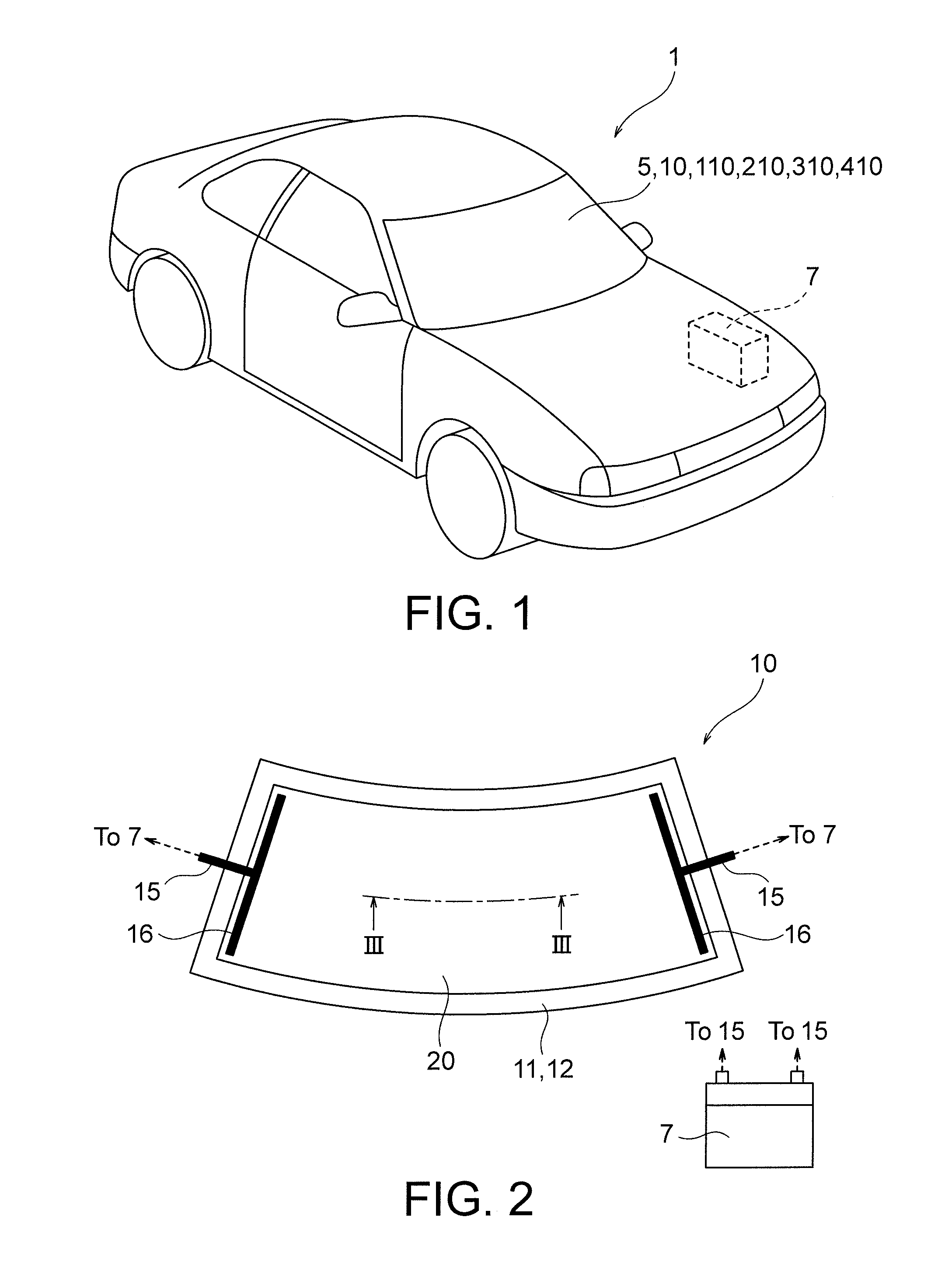
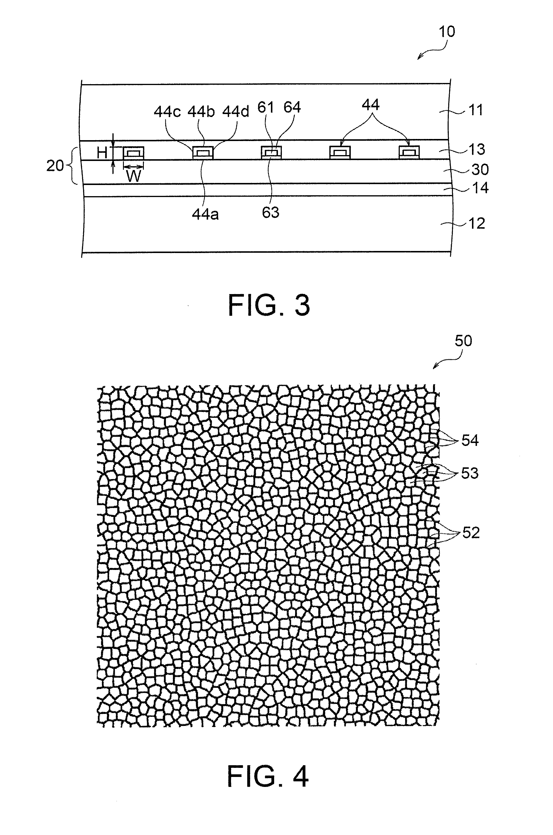
[0223]FIGS. 1 to 22 are views for explaining a first embodiment according to the present invention. FIG. 1 is a view schematically showing an automobile including a heating plate. FIG. 2 is a view of the heating plate when viewed in a normal direction of a plate plane thereof. FIG. 3 is a cross sectional view of the heating plate of FIG. 2. The heating plate in this embodiment is sometimes referred to as “laminated glass”.

[0224]As shown in FIG. 1, an automobile 1 as an example of a vehicle includes panes such as a front window, a rear window and side windows. Herein, a front window 5 is formed of a heating plate 10 by way of example. In addition, the automobile 1 includes a power source 7 such as a battery. Heating plates 110, 210, 310 and 410 according to the other embodiments described below can be applied to the automobile of FIG. 1.

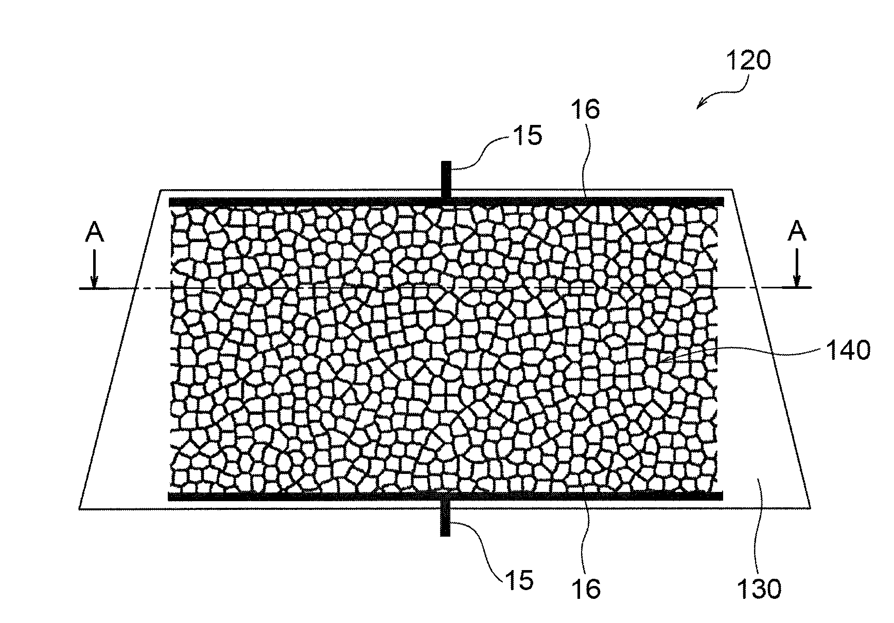
[0225]FIG. 2 shows the heating plate 10 viewed in a normal direction of a plate plane thereof. In addition, FIG. 3 shows a cross-sectional view corre...

second embodiment

[0287]FIG. 1 and FIGS. 24 to 42 are views for explaining a second embodiment according to the present invention. In the second embodiment described below, a component corresponding to that of the first embodiment is shown by a symbol in 100s with the same last two digits, and overlapped description is omitted.

[0288]FIG. 24 is a view of a heating plate when viewed in a normal direction of a plate plane thereof. FIG. 25 is a sectional view of the heating plate of FIG. 24. The heating plate in this embodiment is sometimes referred to as “laminated glass”.

[0289]FIG. 24 shows a heating plate 110 when viewed in a normal direction of a plate plane thereof. FIG. 25 is a cross-sectional view corresponding to a XXV-XXV line of the heating plate 110 of FIG. 24. In the example shown in FIG. 25, the heating plate 110 includes a pair of glass plates 111, 112, a conductive pattern sheet (pattern sheet) 120 disposed between the pair of glass plates 111, 112, a joint layer 113 that joins the glass p...

third embodiment

[0359]FIG. 1 and FIGS. 43 to 56 are views for explaining a third embodiment according to the present invention. In the third embodiment described below, a component corresponding to that of the first and second embodiments is shown by a symbol in 200s with the same last two digits, and overlapped description is omitted.

[0360]FIG. 43 is a view of a heating plate when viewed in a normal direction of a plate plane thereof. FIG. 44 is a cross sectional view of the heating plate of FIG. 43. FIG. 45 is a view showing conditions of respective members constituting the heating plate of FIG. 44 before the respective members are laminated. The heating plate in this embodiment is sometimes referred to as “laminated glass”.

[0361]FIG. 43 shows a heating plate 210 when viewed in a normal direction of a plate plane thereof. FIG. 44 is a cross-sectional view corresponding to a XLIV-XLIV line of the heating plate 210 of FIG. 43. The heating plate 210 includes a pair of curved glass plates 211, 212, a...


PUM


Abstract

A heating plate 10 includes: a pair of glass plates 11, 12; a conductive pattern 40, 70 disposed between the pair of glass plates 11, 12 and defining a plurality of opening areas 43, 73; and a joint layer 13, 14 disposed between the conductive pattern 40, 70 and at least one of the pair of glass plates 11, 12; wherein the conductive pattern 40, 70 includes a plurality of connection elements 44, 74 that extend between two branch points 42, 72 to define the opening areas 43, 73; and a rate of the connection elements 44, 74, which are straight line segments connecting the two branch points 42, 72, relative to the plurality of connection elements 44, 74, is less than 20%.

Description

TECHNICAL FIELD[0001]The present invention relates to a heating plate, a conductive pattern sheet for the heating plate, a vehicle having the heating plate, and a method of manufacturing the heating plate.BACKGROUND ART[0002]As a defroster apparatus used for a pane, such as a front window and a rear window of a vehicle, a defroster apparatus locating a heating wire formed of a tungsten wire or the like all over the pane is known. In the conventional technique, by powering the heating wire provided all over the pane to raise a temperature of the pane by means of resistance heat, the pane is defogged or defrosted to ensure a field of view of a passenger.[0003]In a defroster apparatus disclosed in JP2013-173402A, a tungsten wire is used as the heating wire. In this case, the heating wire has an increased cross-sectional area in order to prevent that electric resistance of the heating wire becomes too high because of a higher electric resistivity of tungsten. Thus, the heating wire usin...

Claims


Application Information

Patent Timeline
Patent Type & Authority Applications(United States)
IPC IPC(8): B60S1/02H01C17/00B60S1/58
CPCB60S1/026H01C17/003B60S1/586H05B3/84H05B2203/002H05B2203/005H05B2203/007H05B2203/011H05B2203/014
Inventor SUETSUGU, HIROTOSHIHIRAKAWA, MANABUGOISHIHARA, SATOSHIKINOSHITA, KOICHINAKAMURA, HIDENORIOHKAWA, KOUJIROMATSUKURA, TETSUOINOUE, ISAO
Owner DAI NIPPON PRINTING CO LTD
Why Eureka
Try Eureka