Electrically heated filter screens

a filter screen and filter screen technology, applied in the direction of filtration separation, turbine/propulsion fuel heating, separation process, etc., can solve the problems of fuel system ice formation, fuel tank ice formation, conduit, valve, etc., and achieve the effect of preventing ice formation

Active Publication Date: 2016-10-27
RTX CORP
View PDF0 Cites 6 Cited by
  • Summary
  • Abstract
  • Description
  • Claims
  • Application Information

AI Technical Summary

Benefits of technology

[0013]The EHFS can be captive in a union fluidly coupling adjacent upstream and downstream fuel conduits. It is contemplated that the metallic layer of the heating bodies face upstream, into fuel flowing from the upstream conduit and into the downstream conduit, and that the EHFS be configured and adapted to melt ice entrained in the fuel flow as well as protect the insulating layer and heating element from impact of ice particles entrained in the fuel flow.

Problems solved by technology

In extremely cold operating environments such fuel systems are susceptible to ice formation in fuel tanks, conduits, valves, and other system components.
Ice formation can occur when either fuel or water contaminating the fuel is exposed to low temperature for extended time periods.

Method used


Image

  • Electrically heated filter screens
  • Electrically heated filter screens
  • Electrically heated filter screens

Examples


Embodiment Construction

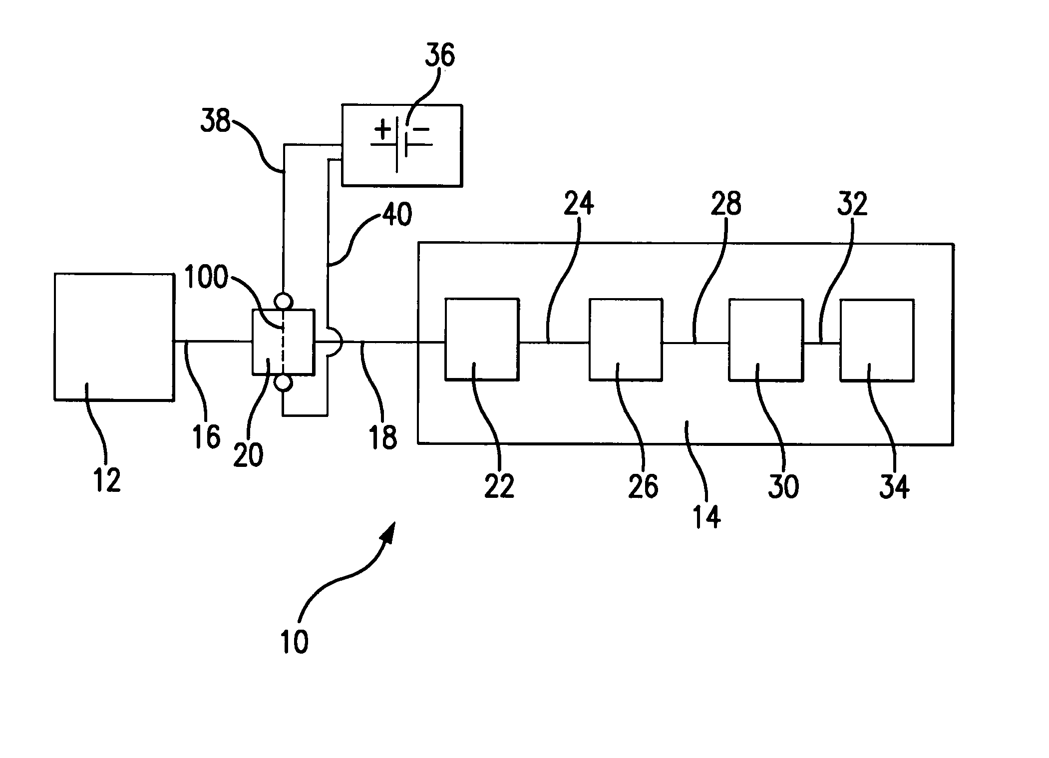
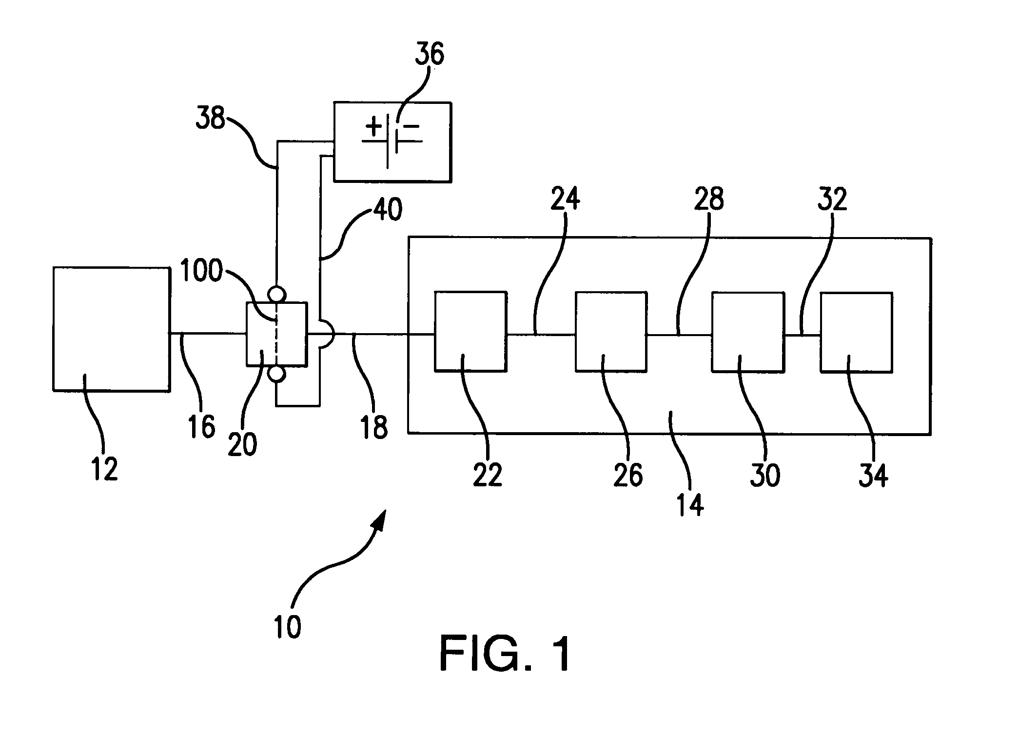
[0022]Reference will now be made to the drawings wherein like reference numerals identify similar structural features or aspects of the subject disclosure. For purposes of explanation and illustration, and not limitation, a partial view of an exemplary embodiment of an electrically heated filter screen (EHFS) in accordance with the disclosure is shown in FIG. 1 and is designated generally by reference character 100. Other embodiments in accordance with the disclosure, or aspects thereof, are provided in other figures, as will be described. The system of the disclosure can be used for gas turbines such as aircraft main and auxiliary power unit (APU) engines. As will be appreciated embodiments of the EHFS disclosed herein are also suitable for use in marine or terrestrial gas turbines.

[0023]With reference to FIG. 1, a fuel system 10 for an aircraft is shown. Fuel system 10 includes a fuel tank 12 fluidly coupled to a turbojet fuel system 14 by a conduit 16, a union 20, and a conduit 1...


PUM

PropertyMeasurementUnit
metallicaaaaaaaaaa
cross-sectional areaaaaaaaaaaa
insulatingaaaaaaaaaa

Abstract

A heating body for an electrically heated filter screen includes a heater element having an outer surface and a metallic protective layer having an inner surface. An insulating layer is disposed between the heater element outer surface and the inner surface of the metallic layer. The metallic layer and an exposed portion of the insulating layer define an exterior of the heating body. An electrically heated filter screen constructed from pairs of intersecting heating bodies is also described.

Description

RELATED APPLICATIONS[0001]This application claims the benefit of and priority to U.S. Provisional Patent Application No. 61 / 842,575 filed Jul. 3, 2013, the contents of which are incorporated herein by reference in their entirety.BACKGROUND OF THE INVENTION[0002]1. Field of the Invention[0003]The present disclosure relates to electrically heated filter screens, and more particularly to electrically heated filter screens with metal protective layers for aircraft fuel systems.[0004]2. Description of Related Art[0005]Gas turbine engine fuel systems operate in wide range of environmental conditions. In extremely cold operating environments such fuel systems are susceptible to ice formation in fuel tanks, conduits, valves, and other system components. Ice formation can occur when either fuel or water contaminating the fuel is exposed to low temperature for extended time periods.[0006]To combat icing, electrically heated filter screens can be provided within the fuel system. Electrically h...

Claims


Application Information

Patent Timeline
Patent Type & Authority Applications(United States)
IPC IPC(8): B64D37/32B01D35/18H05B3/16B01D35/00B64D37/34F02C7/224
CPCB64D37/32B64D37/34F02C7/224H05B2203/024B01D35/005B01D35/18H05B3/16
Inventor FAUSETT, TAYLORWASSON, PATRICK M.
Owner RTX CORP
Why Eureka
Try Eureka