Eureka AIR delivers breakthrough ideas for toughest innovation challenges, trusted by R&D personnel around the world.

Object recognition device

Active Publication Date: 2016-10-27
HITACHI LTD
View PDF3 Cites 2 Cited by
  • Summary
  • Abstract
  • Description
  • Claims
  • Application Information

AI Technical Summary

Benefits of technology

The present invention allows for the collection of dense distance data across an estimated plane region, which enables the detection of small and remote objects that may be hidden between radar scan positions. Additionally, the invention provides information about the distance of an object located outside the radar's detection range.

Problems solved by technology

On the other hand, cost reduction has always been strongly demanded of an automobile, and the cost reduction is an important issue for a safety system as well.
Thus, object recognition and position detection are difficult by using the radar only.

Method used


Image

  • Object recognition device
  • Object recognition device
  • Object recognition device

Examples


Embodiment Construction

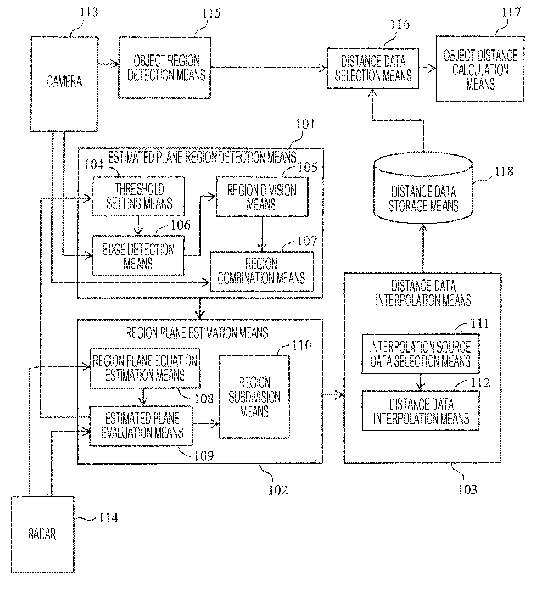
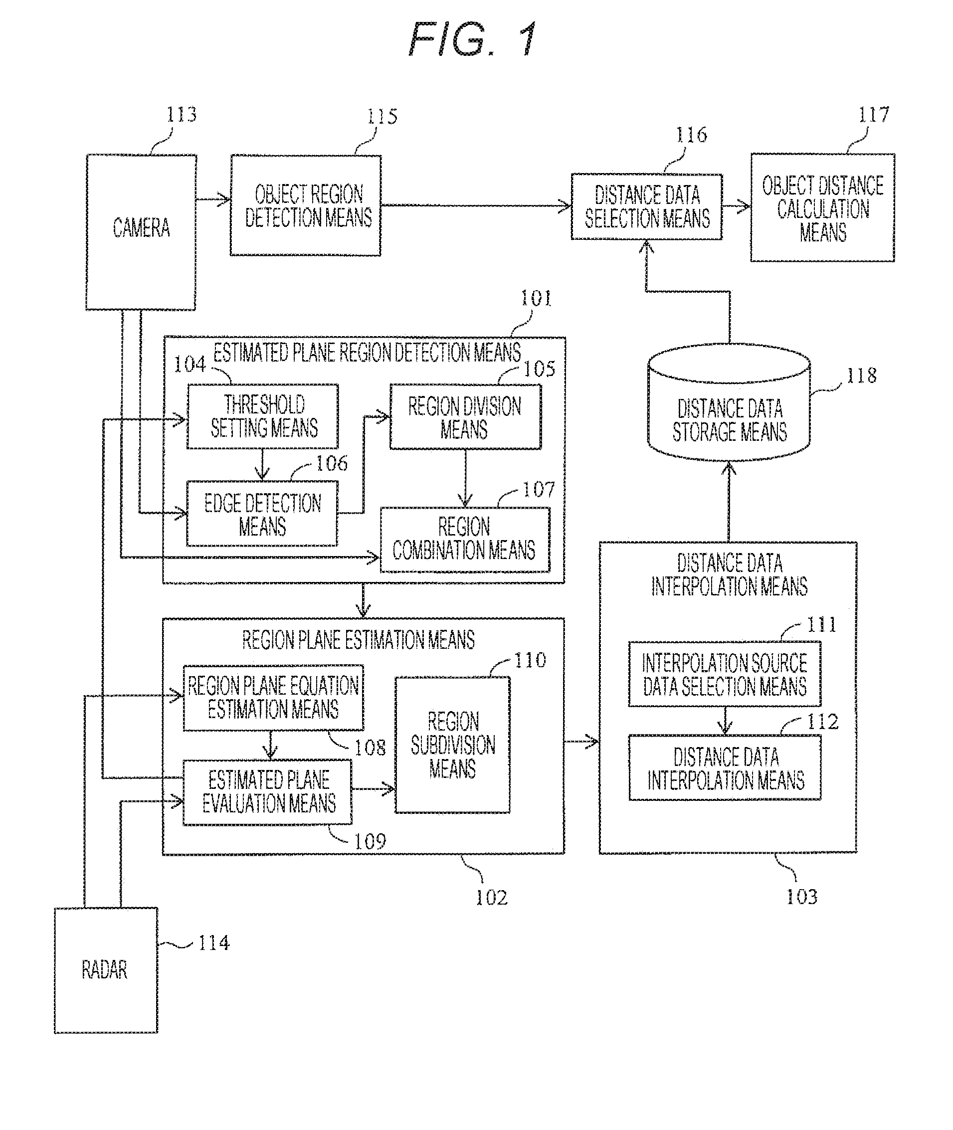
[0021]Next, an embodiment of the present invention is described by using the drawings hereinafter.

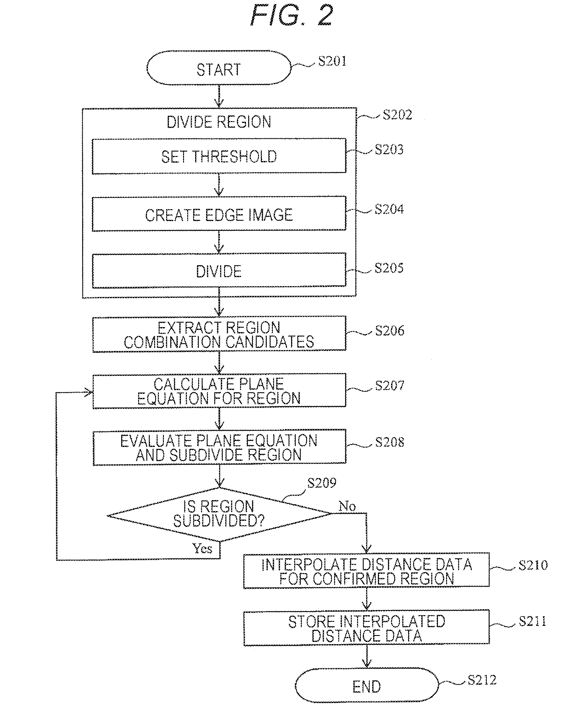
[0022]An object recognition device according to this embodiment is mounted on a vehicle and is configured to recognize, for example, an object ahead of the vehicle such as a proceeding vehicle based on an imaged image from a camera and measured distance data from a radar. The object recognition device can be used for obstacle avoiding and autonomous travelling.

[0023]The object recognition device is configured to extract at least one or more estimated plane regions estimated to be a plane from an image, to verify whether or not the estimated plane region that has been extracted is a plane based on the measured distance data from the radar, and in the estimated plane region that has been verified to be the plane, to estimate a distance to a position, for which there is no measured distance data, by interpolating the measured distance data within the estimated plane region, and to improve ...


PUM


Abstract

An object recognition device includes a camera (113) and a radar (114), detects an estimated plane region estimated to be a plane from an image from the camera (113) (S202), and calculates a plane equation for the estimated plane region (S207). The object recognition device interpolates and estimates distance data within the estimated plane region based on the plane equation and the measured distance data from the radar (S210) and obtains the distance to an object by using the distance data. Accordingly, it is possible to obtain dense distance data throughout the estimated plane region and to detect the distance to small objects and distant objects.

Description

TECHNICAL FIELD[0001]The present invention relates to an object recognition device that recognizes an object based on measured distance data from a radar and an image from a camera.BACKGROUND ART[0002]To reduce automobile accidents and improve automobile safety, a safety system technology for detecting an obstacle and avoiding the obstacle or notifying a driver thereof is important. Furthermore, to reduce a load on the driver and obtain further safety, an autonomous travelling technology for recognizing a shape of unevenness, a bump, and the like of a road surface and for detecting travelable region is demanded.[0003]On the other hand, cost reduction has always been strongly demanded of an automobile, and the cost reduction is an important issue for a safety system as well. In the object recognition device mounted on the automobile, a range finder such as a light detection and ranging (LIDAR) (laser radar) and a millimeter wave radar is used; however, to achieve the cost reduction o...

Claims


Application Information

Patent Timeline
IPC IPC(8): G01S13/93G08G1/16G06K9/00G01S13/86G01S13/931G01S17/86G01S17/931
CPCG01S13/931G06K9/00791G08G1/166G01S13/867G01S2013/9323G01S17/931G01S17/86G06V20/56
Inventor KURATA, KENICHIROUMATSUO, SHIGERUHASEJIMA, NORIYASU
Owner HITACHI LTD
Why Eureka
Eureka Blog
Learn More