Continuous use syringe filter

a technology of syringe filter and continuous use, which is applied in the field of filtration devices, can solve the problems of time-consuming and burdensome for users, and increases the risk of contamination of the solution to be filtered, and achieves the effect of low cos

Active Publication Date: 2016-11-03
GLOBAL LIFE SCI SOLUTIONS GERMANY GMBH
View PDF1 Cites 6 Cited by
  • Summary
  • Abstract
  • Description
  • Claims
  • Application Information

AI Technical Summary

Benefits of technology

[0015]In a further embodiment, the housing comprises one or more projecting members that abut with the filter carrier and / or the filter when liquid is being drawn into the apparatus, thereby ensuring that the second opening is not sealed by the movement of the filter carrier or filter as liquid is being drawn into the apparatus. In a further embodiment, the second wall of the housing comprises an inner face, and the inner face comprises one or more of such projecting members that abut with the filter carrier and / or the filter when liquid is being drawn into the apparatus, thereby ensuring that the second opening is not sealed by the movement of the filter carrier or filter as liquid is being drawn into the apparatus. The projecting members may comprise a plurality of ribs extending radially from the second opening. In a further embodiment, the housing comprises opposed spaced apart first and second walls separated by a side wall, and the ribs further extend down the inner surface of the side wall. The ribs on the inner surface of the side wall can guide the movement of the filter carrier to ensure the horizontal surface of the filter is maintained in a plane that is substantially perpendicular to the direction of the side wall.

Problems solved by technology

This can be time consuming and burdensome for the user.
Furthermore, the need to move the syringe between filtration steps and to remove and re-attach the filter increases the risk of contamination of the solution to be filtered.

Method used


Image

  • Continuous use syringe filter
  • Continuous use syringe filter
  • Continuous use syringe filter

Examples


Embodiment Construction

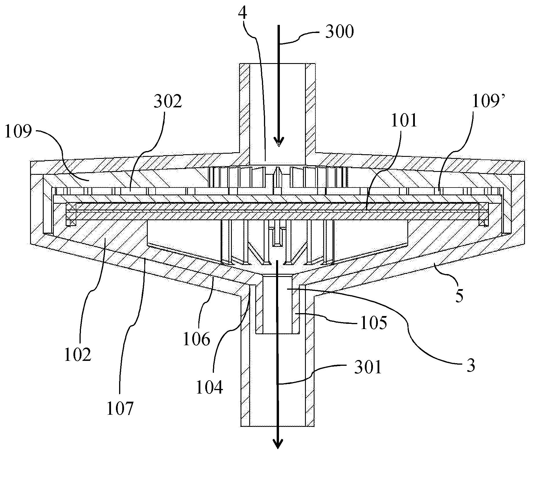
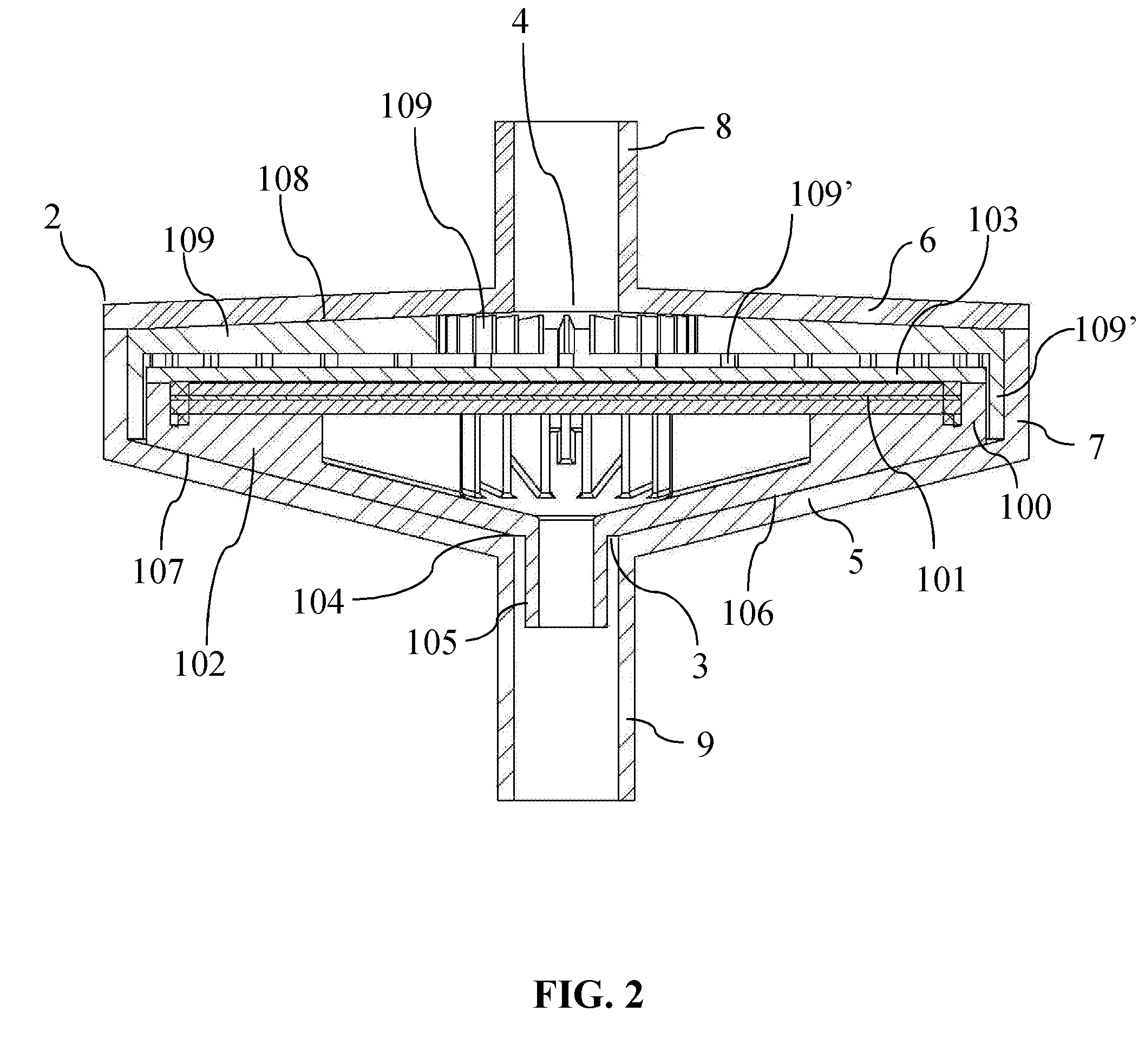
[0032]According to a first aspect of the present invention, there is provided a housing comprising a first opening for connecting to a liquid source, a second opening for connecting with an apparatus for drawing in and expelling liquid, and a valve means comprising a filter carrier and a filter, the filter carrier supporting the filter and being movable within the housing; wherein the valve means permits liquid that is drawn into the housing from the liquid source by the apparatus to enter the apparatus by bypassing the filter but which forces liquid that is subsequently pushed from the apparatus through the second opening into the housing to be filtered through the filter.

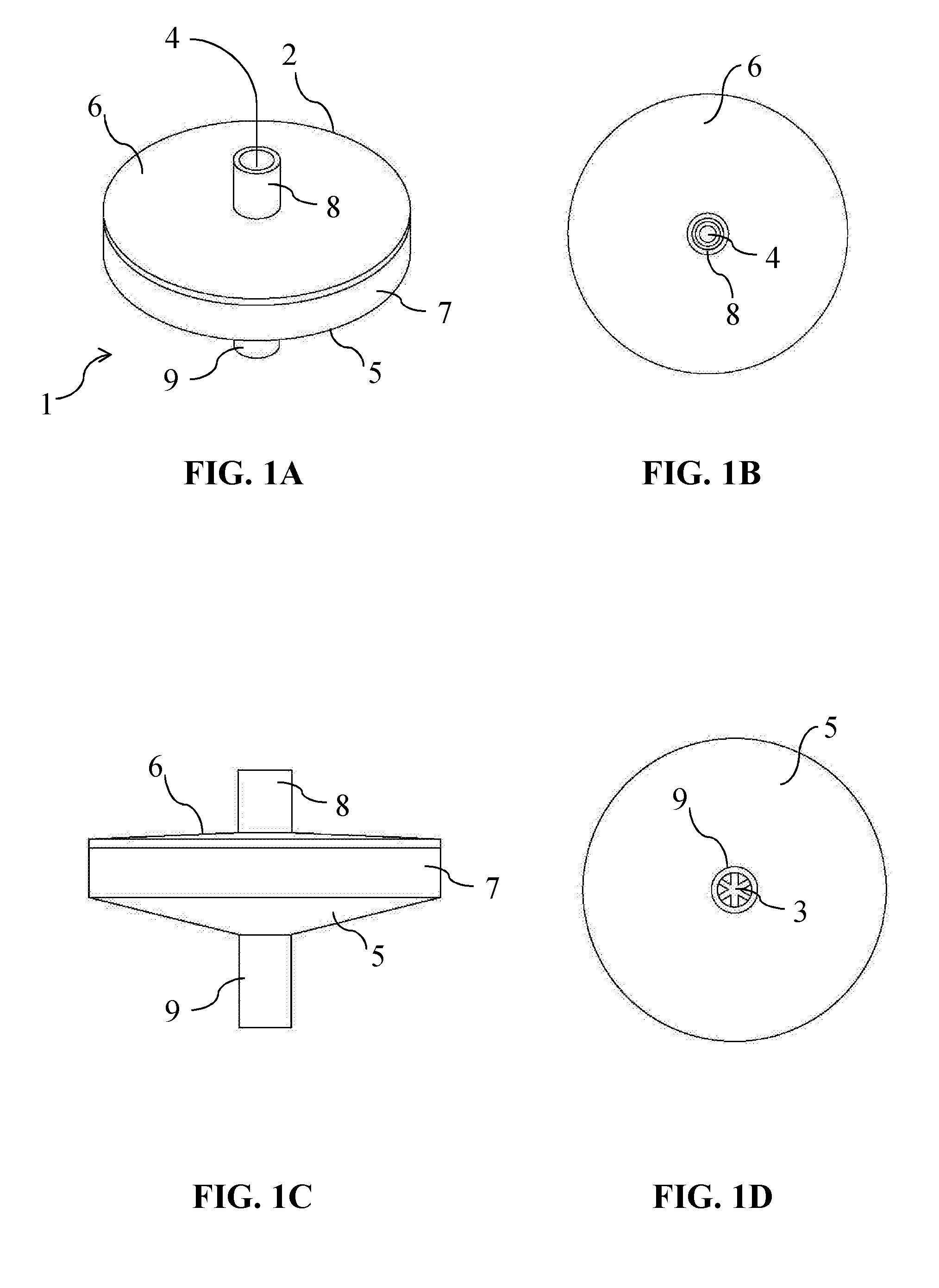
[0033]FIGS. 1A and 1C are three dimensional schematics showing a preferred embodiment of the present invention. FIGS. 1B and 1D are respective top and bottom plan views. The device 1 comprises a housing 2. The housing comprises a first opening 3 for connecting to a liquid source and a second opening 4 for connecti...


PUM


Abstract

The present invention provides a device comprising: a housing comprising a first opening for connecting to a liquid source, a second opening for connecting with an apparatus for drawing in and expelling liquid, and a valve means comprising a filter carrier and a filter, the filter carrier supporting the filter and being movable within the housing; wherein the valve means permits liquid that is drawn into the housing from the liquid source by the apparatus to enter the apparatus by bypassing the filter but which forces liquid that is subsequently pushed from the apparatus through the second opening into the housing to be filtered through the filter.

Description

FIELD OF THE INVENTION[0001]The present invention relates to filtration devices and methods of using such devices to filter solutions.[0002]BACKGROUND TO THE INVENTION[0003]Filtration is a common method of separating larger particles in solution from smaller ones. Filters, filtrations devices and filtration methods are used in a wide range of biological and chemical applications for the separation or purification of various moieties.[0004]Syringe filters are used in the art to filter liquids. Such filters are regularly used for the lab-scale filtration of liquids. The use of such filters typically comprises drawing the sample to be filtered into a syringe. The syringe is then attached to a syringe filter and the liquid is then pushed through the filter.[0005]Often, when extracting a sample that requires filtration it is necessary to filter a volume of liquid larger than the volume of the syringe. In such circumstances, once the user has pushed the liquid from the syringe through the...

Claims


Application Information

Patent Timeline
Patent Type & Authority Applications(United States)
IPC IPC(8): A61M5/31B01L3/00
CPCA61M5/3145B01L3/5635A61M2005/3128A61M2205/75B01L2200/0631B01L2400/06B01L2300/0858B01L2300/08B01L2300/12B01L2300/0681A61M5/165B01L2400/0605G01N2001/4088
Inventor SEYMOUR, GERAINTJAMES, MARTIN DAVIDWEST, RICHARD MARTIN
Owner GLOBAL LIFE SCI SOLUTIONS GERMANY GMBH
Why Eureka
Try Eureka