Butterfly Valve Device

Inactive Publication Date: 2008-07-17
HITACHI LTD
View PDF21 Cites 15 Cited by
  • Summary
  • Abstract
  • Description
  • Claims
  • Application Information

AI Technical Summary

Benefits of technology

[0022]According to the present invention, it is possible to provide a butterfly valve device made of a resin material, which is capable of adjusting the flui

Problems solved by technology

As a result, the adjustment of the minimum flow of the valve becomes unstable, and the minimum flow is easily susceptible secular change.
However, if a throttle valve made of resin is used, there arises a problem that the temperature influence causes a minute gap, which is formed in a fluid sealing member between a throttle valve and an airflow path wall surface, to change so that an allowable value is exceeded.
As a result, there is a possibility that a gap between them will be widened.
In addition, if both of a molded body and a throttle valve, which constitute an airflow path, are formed by resin mol

Method used


Image

  • Butterfly Valve Device
  • Butterfly Valve Device
  • Butterfly Valve Device

Examples


first embodiment

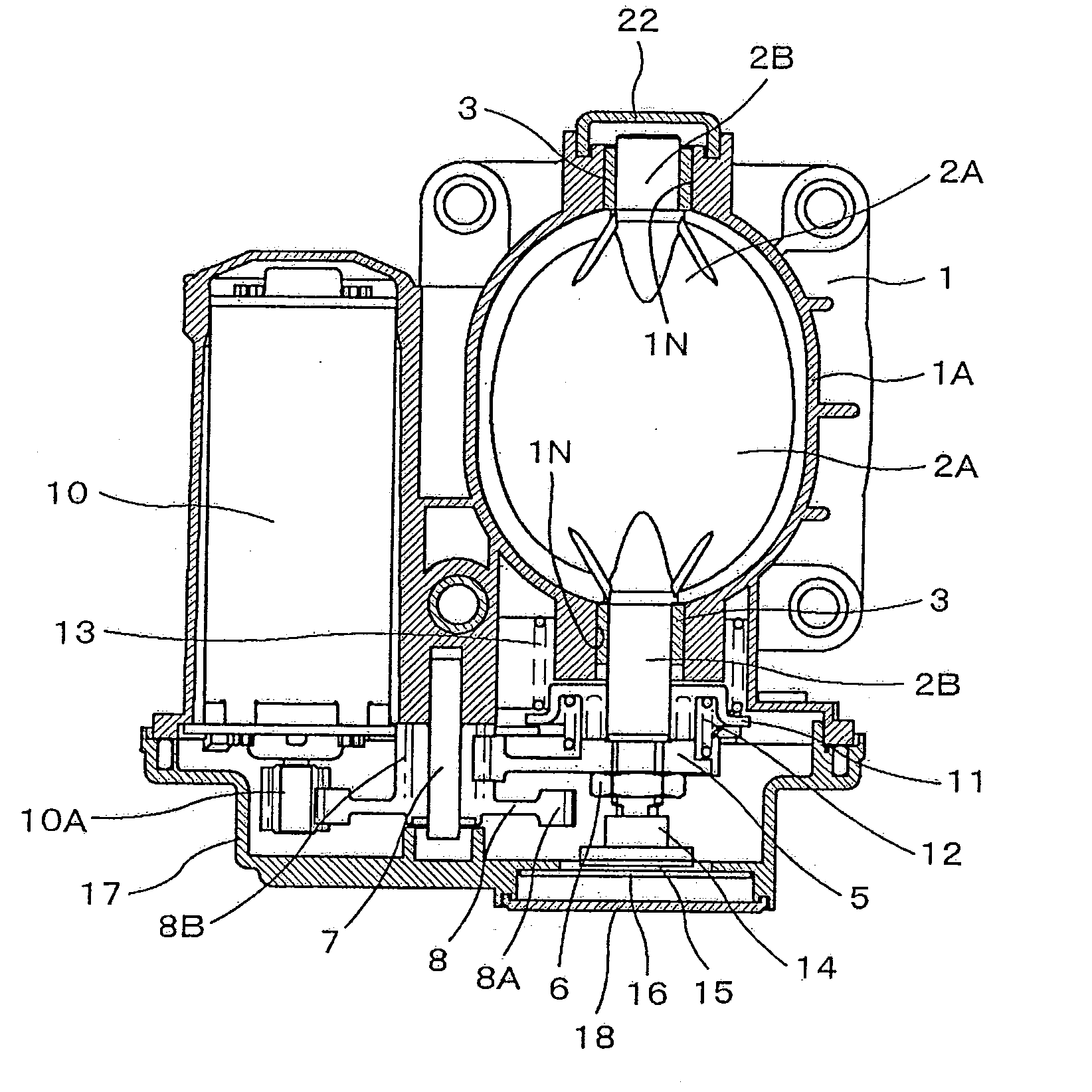
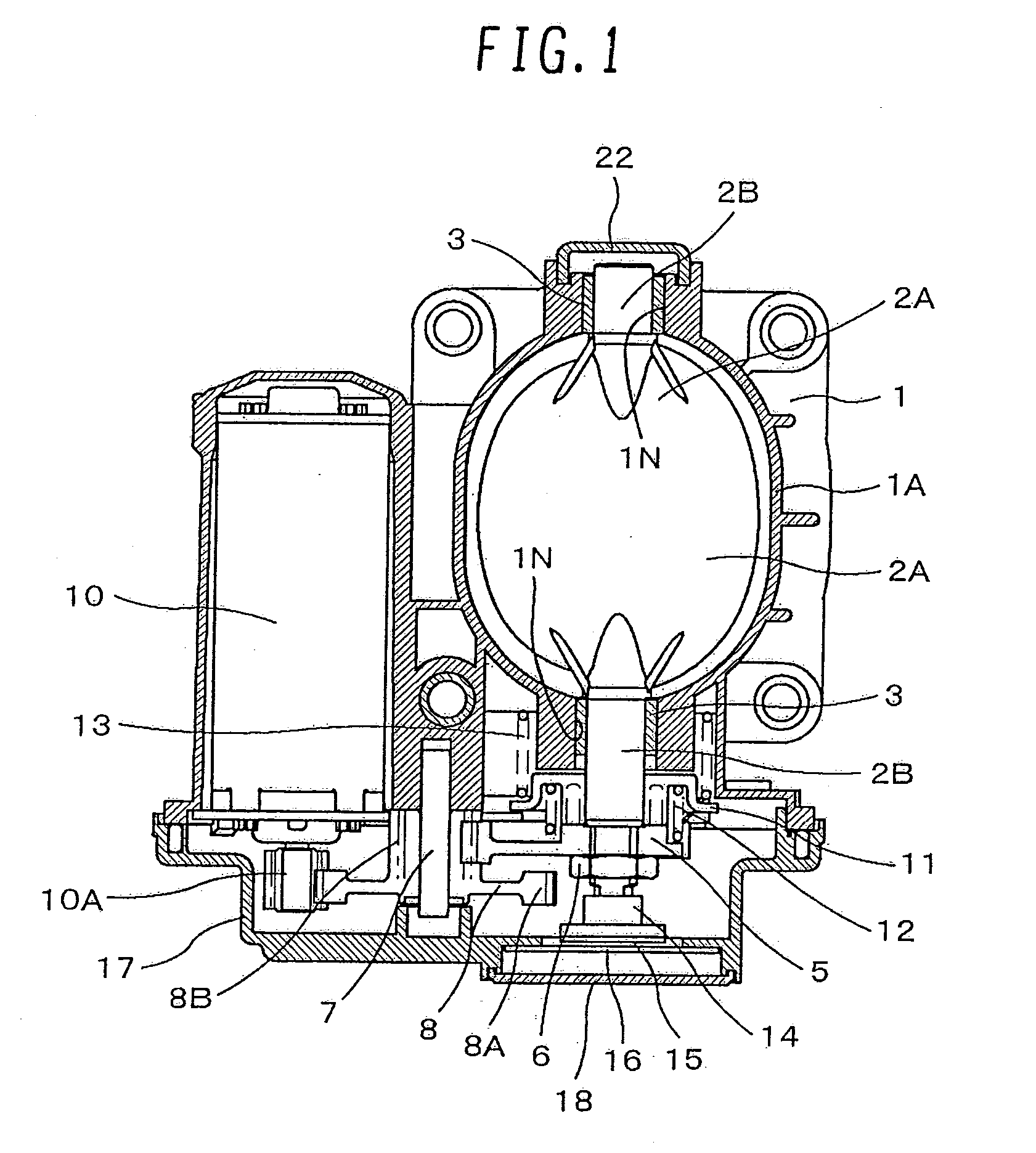
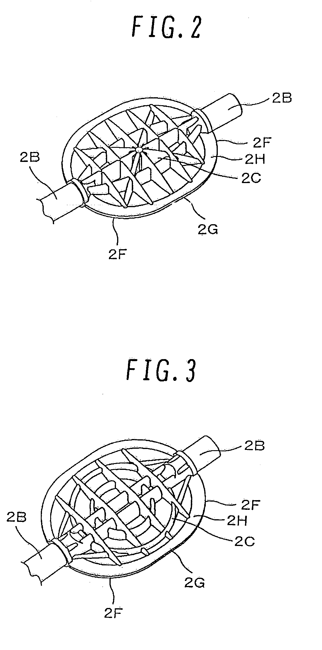
[0067]FIG. 1 is a cross sectional view illustrating essential parts according to an embodiment of the present invention. A motor-driven electronically controlled throttle device includes: a throttle body's internal airflow path 1A that forms part of an intake path of an internal combustion engine; and a throttle valve 2A that is rotationally mounted inside the internal airflow path 1A. The throttle valve 2A and a throttle shaft 2B are molded of resin as one unit. The throttle shaft 2B is supported by slide bearings3, which are made of resin, at both ends of the throttle body's internal airflow path 1A so that the throttle shaft 2B can rotate. A throttle valve shaft 2 cannot be assembled after it is molded of resin together with a throttle body. Therefore, one of the following methods is adopted: molding the throttle valve shaft 2, and then mounting the throttle valve shaft 2 to a shaping die of a throttle body 1 before molding the throttle body 1; molding the throttle body 1, and th...

second embodiment

[0081]FIG. 15 is a diagram illustrating another embodiment of the present invention. The description in the first embodiment is based on the assumption that each of the throttle body's internal airflow path 1A and the throttle valve 2A has a shape of an ellipse. However, R shown in FIG. 15 may also be changed within a range from 0 to L. When R=0, each of the throttle body's internal airflow path1A and the throttle valve 2A has a shape of a rectangle. On the other hand, when R=L, each of the throttle body's internal airflow path 1A and the throttle valve 2A has a shape of an ellipse as shown in FIG. 1. In addition, each of the throttle body's internal airflow path 1A and the throttle valve 2A may also have a shape of a circle or an oval.

[0082]In addition, for each of the throttle body's internal airflow path 1A and the throttle valve 2A, with the objective of further easing the bending of the throttle valve 2A, the throttle body's internal airflow path 1A is divided into two or more ...

third embodiment

[0083]FIG. 16 is a diagram illustrating still another embodiment of the present invention. Even if the throttle body's internal airflow path 1A is provided with the projection 1C on the inside thereof, if the throttle valve 2A opens at the minute opening, the projection 1C may also be provided with a slit 1D as shown in FIG. 16 as a method for decreasing the fluctuations in airflow on the downstream side as shown in FIG. 8. As shown in FIG. 17, the slit 1D may also be provided with a taper in a flow path direction; or as shown in FIG. 18, the slit 1D may also be kept straight. In addition, as shown in FIG. 19, the slit 1D may also be so configured that the entrance side of the slit 1D becomes larger, whereas the exit side of the slit 1D becomes smaller, so that a step is formed therebetween. The size of each slit is determined on the basis of the equalization of the required flow, and from the leakage airflow.


PUM


Abstract

An object of the present invention is to provide a butterfly valve device made of resin, the butterfly valve device being little susceptible the secular change in gas flow (in particular, the minimum flow) or random changes.
According to the present invention, when a butterfly valve is located at a full-closed position facing a peripheral lower surface of a semicircular portion with respect to a rotating shaft of the butterfly valve made of a resin material, a partial annular projection is adapted to radially inwardly extend towards an inner wall surface of a fluid path, the partial annular projection including a plane that contacts the peripheral lower surface of the valve to form a fluid seal. Preferably, while the valve opens only by the thickness thereof from a mechanically full-closed position, from which the valve cannot mechanically rotate any more in a close direction, a surface on the periphery of the valve is formed in a curved surface shape having the specific curvature so that the specified minimum airflow is achieved at the mechanically full-closed position. In addition, cylindrical elastic sealing members are mounted around the shaft in a bearing hole, and an edge on the fluid path side of the sealing members elastically contacts an annular surface formed at a position facing the bearing hole about the rotating shaft of the valve.

Description

BACKGROUND OF THE INVENTION[0001]1. Field of the Invention[0002]The present invention relates to butterfly valve devices for controlling the gas flow, and more particularly to valve devices that are formed by resin molding. These butterfly valve devices can be applied to, for example, a throttle valve device for controlling the airflow of an internal combustion engine.[0003]2. Description of the Related Art[0004]For a butterfly valve used for controlling the gas flow, typified by the airflow, the formation of the butterfly valve by resin molding is proposed from the viewpoint of the weight saving, and the formability. As an example, JP-A-2005-163546, JP-A-2005-180423, and JP-A-2005-273563 disclose that a throttle valve for controlling the airflow of an internal combustion engine is formed by resin molding.SUMMARY OF THE INVENTION[0005]However, in the case of the butterfly valve formed by resin molding, the deformation of the valve exerts a large influence upon flow control character...

Claims


Application Information

Patent Timeline
IPC IPC(8): F02D9/08
CPCF02D9/101F02D9/1015F02D9/104F02D9/108F02D9/1055F02D9/106F02D9/1045
Inventor SHIMURA, TAKAHIROBANSE, MASASHIIWAKI, HIDEFUMI
Owner HITACHI LTD
Why Eureka
Try Eureka